I am not sure about this feature. In the Cad side selecting advanced hole there is a provision for selecting threads, I can select this function and it opens several choices for threading. In my case I am using 1/2 13. In the Cad preview after I select thread size, I hit my save and cancel the hole thread pattern does not show up only the hole and it is a default value as provided from the selection chart.
Because of this I am assuming that the only function of the hole selection is to set the min size of the hole for future threading. In as much as I am using this as a creator tool for STL files for a 3D printer it apparently does not out put the geometry for the hole with threads and when I print I don’t get the threads in the hole .Must be doing something wrong?
Can anyone shine some light on this for me. Regards,
Steve
I have no clue still have not played with the advanced hole. But I think if you make a program to thread mill the 1/2-13 and the save the STL file after you run it in sims. you should have what you need. Maybe a work around.
Called Tek support on this question and received the following answer. The Advanced hole feature in cad does not create any threads in the cad file. It only will properly size the hole to the recommended drill size for a given hole. I haven’t tried to thread mill in a Cam side post and then export the file as a STL. Suggestion was made to add a feature request. Regards,
Steve
So did the thread mill from Cam work?
Hello Steve,
You are correct in that the Advanced Holes function does not display the 3d Threads. However, it does store a property in the background with the Thread info that you set. This way, when you use “Hole Recognition” for a CAM Job (Right-click on “Machine Setup - 1” in the CAM Tree and select “Hole Recognition”), it will know what thread is being called out and make a Tapping operation for it.
The Advanced Holes function does give you the correct size of the hole, chamfer, counterbore. However, it does not make a 3d model of the thread.
This is because 3d threads in the software make the .bbcd file very large and can cause performance issues if the file size is too large. This is one reason why we do not make 3d surfaces for the Thread.
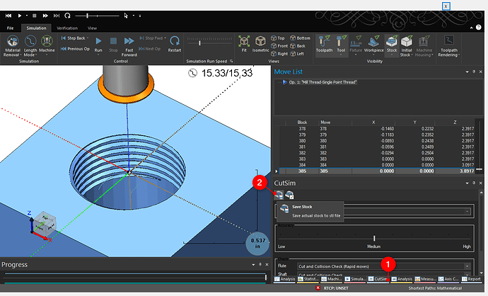
However, if you do want get a 3d model with the Thread in it for 3d printing, I would recommend using the Mill Thread feature on the CAM Side to make a thread toolpath. Then, you can simulate the CAM Job. Once you run through the Job, you can save out the stock as a STL model. Go to Cut Sim > Save Stock:
I hope this helps!
Eric, Thanks. I still have not got this figured out yet. An assumption is I know how to do all the cam stuff like most of you. This is not the case. However, I spent most of the month repairing a spindle drive on my mill and did actually cut a part last Friday on the mill.  This is the first part I have been able to create in Bob Cad and send to the mill and make it work. This is a long story and it involves converting my mill from Fanuc to Masso. I just about have a handle on it now and may actually be able to use it going forward. Regards, Steve
Paul, Thank you for the detailed information, I am sure this will help many others as well. I learned the hard way about the metric output to Cura. Bob Cad does not scale very good in this application and simply output by use of MM is perfect result. I will try the suggestion on creating the threads in cam and then sending the STL file to Cura shortly. My regards, Steve

