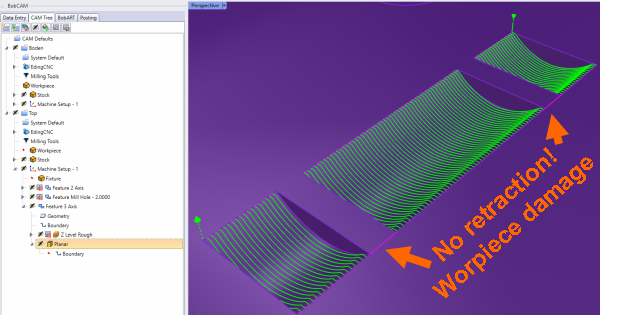
Bug: no retraction between objects => workpiece damage

Hi,
image

image
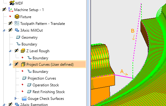
A…no retraction between objects, B…good job on object itself

Today happened the second time to me: within an operation handling multiple geometries, there is no retraction of the z-axis when switching between the objects. Workpiece is damaged for sure (so happened to me) and in stupid situations, a machine crash can occur.

For me, this is an extremely critical bug. Knowing about it, I would also negligently sell a problematic tool to customers.
Regards, Harald

Hi,
Is there any information/confirmation/ongoing about this?
Bye, Harald

If you have not already done so, please contact into support and send your files so they can take a look at it. support@bobcad.com

@TheWeave

I would say to just make them separate operations. But I’m not an expert…

Hey Harald,

You would want to use “Advanced Planar” not the standard “Planar” toolpath. Advanced Planar should actually add a rapid Z move and lift the tool up first before moving tot he new position.

I hope this helps!

Hi @GCSRT,
yes, this is sure a possibility. But soon it will be nerve-racking to make a new operation for several objects. Especially when something has to be changed. Then this has to be done for every operation. Sorry… this is no solution to me, just a workaround.
Bye, Harald

1 Like

Hi,
thanks. I’ll give this a try.
Nevertheless, I see it as problematic if I (or one of my customers) get a milling cutter, workpiece or even spindle shot. This should not happen, because logically the contours are also individual objects. At least I don’t understand and is hard to explain to customers, why there is no retract between them.
Bye, Harald

Harald,

It has to do with the way the “Planar” toolpath is processed with multiple disconnected surfaces in one feature. The “Advanced Planar” toolpath is just able to handle it better. If you only have 3x Standard toolpath, just break it up into multiple features. Otherwise, use Advanced Planar and it should work out just fine.

If you do have 3x Pro toolpath, I always suggest using Advanced Planar, Advanced Z Level Finish and Advanced Rough over Planar, Z Level Finish and Z Level Rough. These are more advanced versions of toolpaths and are able to be modified easier with more functionality.

How to say… I have a little difficulty telling customers about the benefits of BC and at the same time pointing out that there might be “problems”. It would never occur to me that if multiple (unconnected) objects were selected during the milling process, a crash would be produced. Regardless of whether or not that has to do with a “planar” toolpath. Especially where we users will never have the knowledge of internal processes.
Furthermore it is hard to explain to a customer that he has to define 5 times the same operations for 5 objects with the same processing or have to buy the next license version.

I always suggest using Advanced Planar, Advanced Z Level Finish and Advanced Rough over Planar, Z Level Finish and Z Level Rough.

OK… I’ll have to remember that and pass it on.
But how should I do for Project Curves? This is a Premium Operation and lacks with the same problem.
Bye, Harald

I never mentioned Project Curves in this post, but there is a Project Curves Toolpath in both 3x Pro and 3x Premium Toolpath.

If you are concerned about the link move (which is a feed move between cuts) for the standard Planar operation, you can also use “Edit Toolpath” and move it up in the Z direction. There is more than one way to do it. I just tried to give you the easiest way. There is no crashing that happens unless you have a different part from me that is actually causing a crash.

Yeah, but I did in my fist post to this topic (see picture with Project Curves operation).

In my understanding, programs serve to simplify workflows. If I see a possibility for improvement, I try to realize it or point it out. Otherwise there would be no need for further development. Hints on workarounds are great and o.k., because at the momentnothing else is possible. But to leave them permanently does not improve the product.
In the concrete case, the missing retract is a problem to me, because from the user’s point of view it is absolutely not understandable why there is no retract between two boundaries. I do not want want to explain to someone that he should have checked better whether there is a missing retract somewhere in the thousands of G-codes and as a consequence his milling head should therefore be serviced? Furthermore it’s quite a bit hard to search for all missing retracts and correct them manually? Not fun when the milling path is revised and recreated in the course of improvements. There are a lot of other things we have to check/remember/focus when working on/with a machine. Such tasks should not make it worse.

I write these things because they come to me - sometimes during demonstrations for customers and their questions. And they all want security as well as simplicity and extensively compare different CAM software before buying one.

I do appreciate all the feedback. However, If this comes up with a customer, then you can show them how the Advanced Planar toolpath works compared with the Standard Planar. I can put this in as a feature request, but since you can already do this in the software, I don’t know if they will make a change to it. If you are worried about crashing using the Standard Planar, you can always simulate the toolpath as well to see if there is any crashing before you send it to the machine.

If the customer wants a more simple, easier way to use toolpaths with more functionality, then you could recommend getting the 3x Pro module. If you are at all confused by any of this or want more questions answered, you can always give us a call or email at (727) 489 - 0003 or support@bobcad.com and we can help you out. We are more than happy to help!

Our hours are 8 AM EST to 5 PM EST

Have a great rest of your day!