Clearence/Rapid/Feed Plane

Hello all,

is this usual/normal?

I come to this, as due to a huge workpiece the former Clearance Plane (set to 5mm) conflicts with the possible retraction height, that will need some more of 2.67mm my machine doesn’t have (work close to the limit). OK, no problem I thought: put the Clearance Plan to 2mm having a rest of 0.33mm. Well done, the job worked.

Later I realized the Clearance Plane is lower than Rapid Plane and Feed Plane. Does that make sense? Shouldn’t be CP >= RP >= FP? The system didn’t throw a info about that.

Bye, Harald

1 Like

Right click on machine setup, and pick edit. You can change it there.

Actually, you can change rapid/feed plane in the feature itself. IDK what you are asking. Sorry.

Hello,

@GCSRT
The initial question was not how it is possible to change but that it is possible to run into a CP value being smaller than RP and/or FP:
image

Taken from the documentation:

  • Clearance Plane (Mill Jobs):
    the clearance plane is incremental from the top of stock (defined in the Stock Wizard). It defines the safe rapid plane used between machining operations. The value you define in the Machine Setup is applied to all features under that setup.

  • Rapid Plane - is the height at which the tool can rapid safely within a single machining operation. This value is incremental from the Top of Feature setting in the CAM wizard.

  • Feed Plane - is the height at which the tool movement changes from rapid to feedrate. This value is incremental from the toolpath.

Basically, I understand it like this: at the top is the CP level, followed by RP level, and again followed by FP level, with no sublevel gets higher than the level above.

I am curious about your views.
Regards, Harald

In my experience, the machine goes to CP, RP, then FP. Bobcad does do weird things though.

1 Like

Hello,

@MillingGuy, @GCSRT

This is one of the areas of BCC that you have to watch, especially using Mill 2 Axis features. There should be a warning pop up to advise user of this scenario. I am sure you know what you get here is a Z dance before and at the end of the operation. Can scare some “words” out of you when you are not expecting it. Using some Mill 3 Axis features you get a pop up warning/ error message if your RP is below the Z stock value in the Stock setup.

Hopefully @BobCad Support will take a look at this.

Another thing, just like in the scenario in your first post to this topic, there are times you are working on geometry that is below the Top Z0 of your part. In this case if there is higher material in between the geometry selected, you will crash into it, unless the RP has a value that will bring it back up above Z0, in your above case that would be 49.000. For these situations I think having a check box for the RP to be optionally Absolute would be great and avoid the calculation.
I will make this a Feature Request.

3 Likes

Yes, I have crashed the machine because of this. I have never been the same.

1 Like

hmm… IMHO, the different kind of planes should avoid to get machines crashed. If they don’t, isn’t it a big issue to solve/correct. I cannot believe it is the goal to always have to check, if the machine runs in troubles. If it could, the software should either warn for that (at least when doing a post).

I know, it’s

this cannot actually happen if travel paths between different geometries are not run on RP level, but on CP level. This as default with an option that the user can overrule the system telling it should use RP level would already provide the necessary safety here. Or is that a step backwards, because then everything is done at CP level?

Perhaps BC can comment on this?

Bye, Harald

Unlike the Mill 3 Axis toolpaths, Mill 2 Axis toolpaths are non-intuitive, most of the time they will do exactly what is inputted. Of coarse we have the simulation to catch errors. But not all unwanted things are seen in the simulation. In the screen shot below I was able to have RP of -1.500" (shown). This you could miss seeing in the simulator since it is away from the stock.

Screenshot 2021-06-04 093325

So, as for improvements,

Use CP as default (especially when multiple geometry is selected)
A Check Box to optionally use CP
A Check Box to optionally have RP Absolute.

I think a Pop up warning should also be implemented when the Top of Feature is below top of part or stock according to what is set in the job or stock parameters, or if the RP goes below the cut depth. Since Mill 2 axis toolpaths cannot see/use stock or model geometry to detect errors, then is it possible to use the numbers that are inputted in the RP and FP boxes for some kind of warning of user mistake ? I think so.

Any thoughts on this topic ?

@TheWeave, @gmyers

Thanks,
David.

2 Likes

I completely agree. Especially when things have to happen quickly and/or a lot of fine tuning has to be done, it needs something like trust.

Is it? I cannot believe. Just doing 2 axis operatione there there is a stock definition with all dimensions.
Understandable, that collision detection is sure not easy to handle. But that’s also what users rely on with cam software.

Already makes two with the same thought :wink:

Bye, Harald

Hi,

ARRGHH…

did 4 trials to get the final version. The fourth one looks like this and should be go to the customer’s front panel:

Because there are already pockets, I thought to optimize the last operation not to mill in the air and set the Top of the Feature to -12.2mm. Voila: got this:
image
instead of
image
and destroyed the front plate the customer brought to me :rage:

Hey… BC-Team: this is no fun. It is in no way logical that I have to set RP to 17.2 here to get the actual 5mm!

So… now I’m curious how the customer reacts to the “aesthetically” corrected version :unamused:
image

I appeal vigorously to fix this bug! See postings above. I am also a little disappointed that BC has not yet issued a statement on this topic.

Bye, Harald

1 Like

Hi Harald,

Been there and done that !. As I am sure many have also. Sure would be good to hear what BC has in planning for this. Things like this shouldn’t happen and as we have discussed previously in this post, there should be a pop up warning that your RP is below the part top and options to use CP when multiple geometries are selected in one feature operation.

agree my fix for that is to have the feed plane 2.5mm above the total depth. that seems to take out the dog legs also I think the New controls on the Haas you can change a setting to take out dog legs have not used it we have both controls so I just see bad things happen

@Eric: cannot follow the content of your last post :frowning:

To me, CP and RP must always be handled from top of material. No matter which machine or control system is behind it. And a change in “Top of Feature” or whatever else must not result in a change in absolut CP or RP. Meaning e.g. CP = 10mm and RP = 5mm BobCAM always makes CP=10mm and RP=5mm regardless what changes will be done inside the operations.

Bye, Harald

I made a short video to help explain how the system uses Clearance Plane and Rapid Plane in 2 Axis and 3 Axis features. Hopefully this will help you understand why you are getting what you are getting in your part. It is not a bug, but rather a misunderstanding of how these values are intended to be used.

HTH

Alex

2 Likes

Hello Alex,

thanks for the video. yeah… V34 :wink:

All understood. It was before.

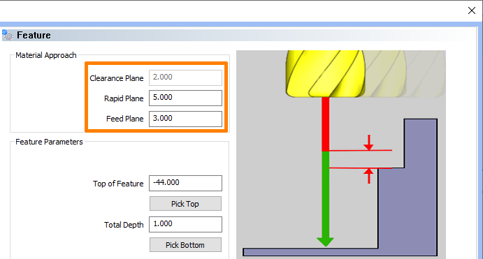
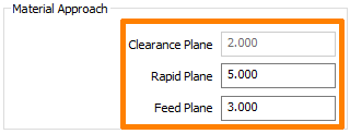
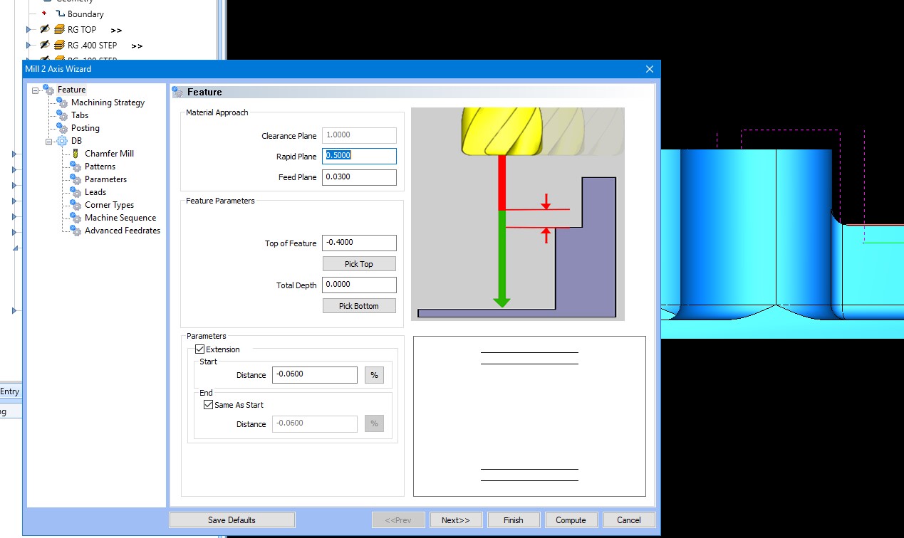
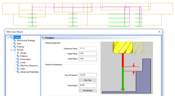
By “bug” I did not mean to eliminate an error from the system, but the elimination of pre-programmed operating errors. Not rarely it comes to pick a “Top of Feature” below 0.00. But also oftne it comes to

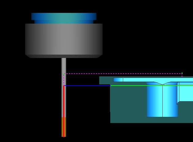
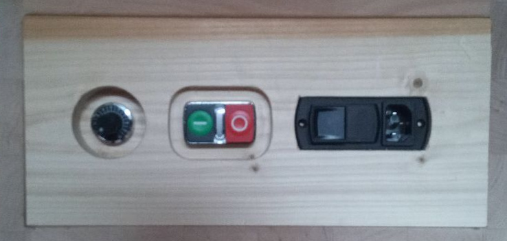
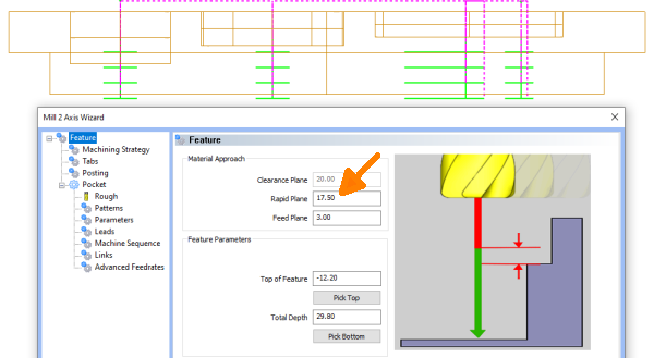
  1. to a crash, if one forget to correct the RP value (as shown in your video going through the workpiece between upper and lower pockets).

or

  1. you do group all pockets of different depth and must therefore calculate each RP to get the same (optimized) height or be at least above a crashing route.

It would not come to such problems if:
BobCAM handles the RP as absolute value from Top of Stock and does not change it on its own. If the user wants to, he should explicit change the value hopefully knowing he had done so :wink:
At least a warning should be thrown, if “Top of Feature” is changed, that this affects the RP. But still has the risk to simply click away the message and drive a crash.

Perhaps a field lock would also help, preventing a value change. Neither BobCAM nor the user can change the value when the field lock is active (default). But it is the user who can remove/set this lock.

Automation is beautiful and great. Unfortunately, when it results in automatic errors, it’s not.

Bye, Harald

2 Likes

It sure would be nice if these values could be toggled between absolute and incremental. Would cut out a lot of confusion and add value to this software.

4 Likes

Hi,

long ago …
Because I still keep running into problems or need time to resolve conflicts with CP, RP and FP: will there be anything new?

Bye, Harald

2 Likes

I hope so.
I run into issues with this too, especially when doing a copy and paste, and the geometries picked are below top of part and you forget to add the necessary height to RP to clear the in between geometry.

I think it should be an easy thing to take care of.

Hopefully it will be addressed in V35. Although, the only BC input into this topic has been @Alex video.

1 Like

Hi,
sadly, no enhancement is given in V35/BC4RH_V3. Maybe in V36/BC4RH_V4?
What’s BC-Team saying about?
Bye, Harald

2 Likes

Yes, it sure would be good to have this taken care of. Not sure why BC don’t see the need for it.

David.

1 Like