Hey Rosco,
Just wanted to give a bit more feedback on this since it popped up in the recent discussions. It is tough to say the exact steps you need to take for your part since there are different ways to approach this and I can not see the .bbcd file.
However, when talking about Boring with a Boring Bar Lathe Tool, use the “Lathe Turning” feature with an “ID” “Feature Type”. Then, on the Tool page, go to the “Tool Crib” > Select the “BORING” Tool Category and select “Add from Tool Library” to add a Lathe Boring Bar.
Note: That the default Lathe Tool Holders do not have capabilities to be cylindrical. You can use the dimensions on the Tool Library to setup the Length and Width of the Tool Holder. Then, when you load simulation, it will give the boring bar no thickness so that it does not collide with the stock.
If you want to see the 3d model of the cylindrical boring bar, you can use machiningcloud.com (MachiningCloud WebApp) and import a 3d model of your lathe tools into BobCAD. MachingCloud is now a paid service. However, you can still access Kennametal tools for free through this portal: NOVO WebApp
(How to Import Tool into BobCAD using machingingcloud)
To address your specific workflow:
-
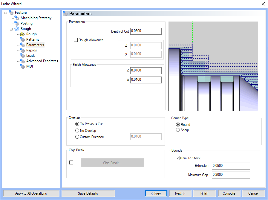
Let’s say you have you actually have the Drill operation as the first feature in the job, when you make the Lathe Turning Feature, enable “Trim to Stock” on the Parameters page. The software will understand what material the Drill operation removed and will trim the toolpath in your ID turning cycle to get rid of the extra moves.
-
If you do not have a drill operation, you can setup your Stock with the “Revolve” option to create a stock that already has the center of the stock removed. Then, when you setup the default ID turning feature, the default Constraints on the initial “Feature” page should already be set to “From Stock”. The software will see that there is no material there and will not create toolpath there.
-
Finally, you can also use the “Custom” Top of Feature Constraints on the initial “Feature” page to setup a distance of how far you want to create toolpath from the tip of the geometry selected in the feature.
I hope this helps someone in the future!
As always, you guys can contact our support team if you have an issue with the software or our training team if you want to schedule a training session to learn the software one-on-one.
Email: support@bobcad.com
Phone Number: (727) 489 - 0003