Hello,
So, I have some notes about the collision detection for the fixture.
First question is, do you have Machine Sim Pro (where you can actually view the machine in simulation).
If no, the simulation uses a default machine in the background that is just called BobCAD_Sim in the MachSim folder. Currently, this XML machine file does not simulate a collision check for the fixture as it is not being output. I have spoken with development and they do plan on adding this to the default machine in the future, but currently it does not collision check.
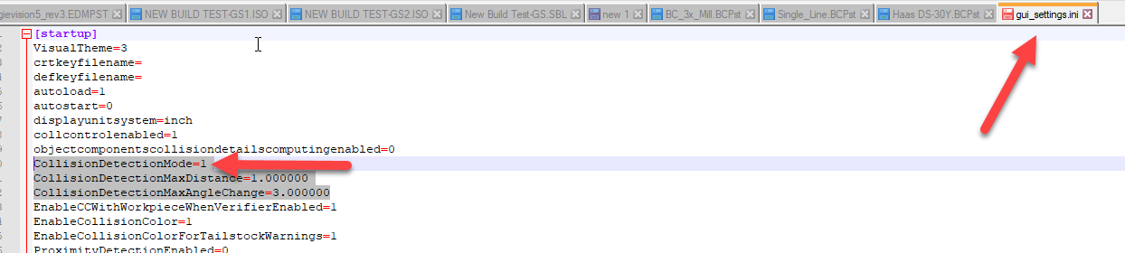
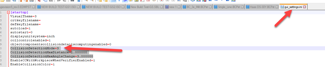
If you do have Machine Sim Pro, then it will use your machine’s XML file in the MachSim folder. For instance, if you have a Haas 3x Mill, you can go to the MachSim folder in the BobCAD-CAM Data folder and find your Haas machine. If you open the folder, there will be an XML file for it. If you edit that XML, there should be a line in there for collision checking and you should see the fixture show up there. (like you see in the picture below)
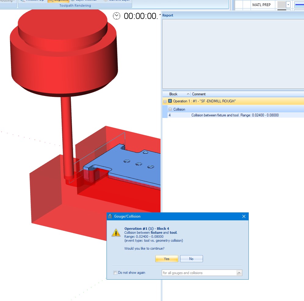
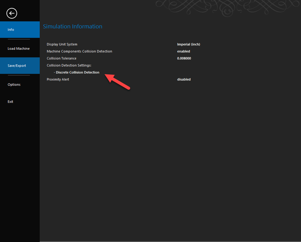
So, if you have Machine Sim Pro and you have verified that your machine XML file does include the fixture, then it should be gouge checking for the fixture when running through the simulation.
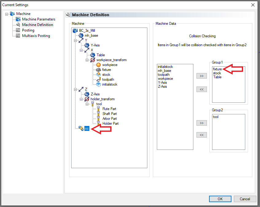
Another area you may need to check though if this is not the case is the Machine Definition (Right-click on CAM Defaults in the CAM Tree and select “Current Settings”. Select your machine from the drop-down box and go to “Machine Definition”.) In the “cc” section you will want to make sure that your fixture is added to the “Group 1” category, like you see below:
If it’s not, go ahead and add it. Then, make sure to re-select your machine in the job to refresh it and try again.
Those are the things you can check to make sure you can gouge check the fixture for simulation.
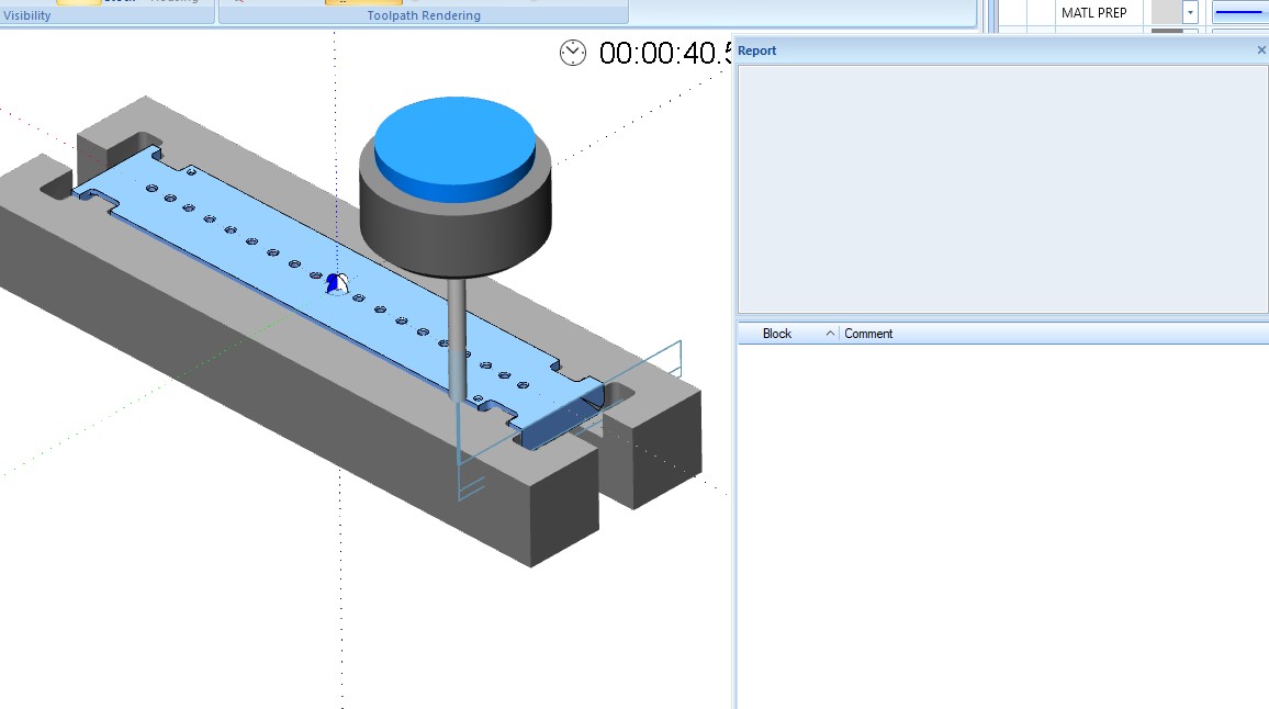
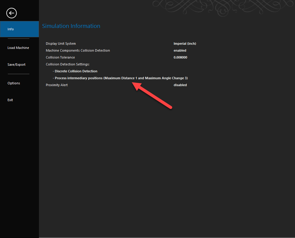
I will end with one more note. There is technically one other reason that you may not be getting a gouge when running a simulation. That is if your start/end points of your toolpath are not inside of the fixture. So, technically, you could have a toolpath that goes through your fixture, but the start and end point of the line/arc is not inside/touching the fixture. However, this would be a very rare case and is likely to not be your issue. If it is, I do believe that there is a setting that can be changed somewhere in the options of the simulation to have it check in more locations along the toolpath, but I do not know offhand where that would be.
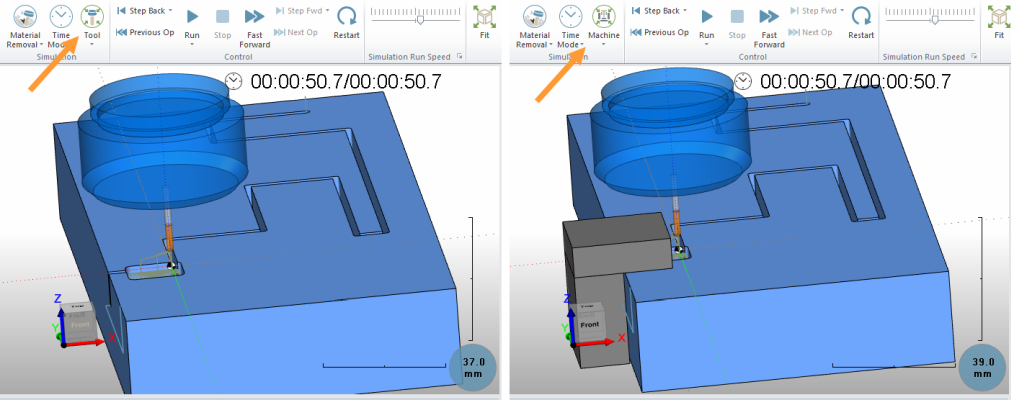
Just by looking at the picture though, my guess is that you do not have Machine Sim Pro and that would be the reason that there is no collision checking at this time.
I hope all this makes sense to you guys! Let me know if you have further questions on this!