
I am currently attempting a new project with a ‘Mill 2 axis’ feature. When creating the feature I have selected the pattern for G41 compensation. When I post the program, I am not seeing any G41/G40s throughout the entire program. This post has been modified by another programmer because “BobCAD’s post for a Haas VF6 didn’t work correctly”. He claims if the programming isn’t outputting G41/G40, I am doing something wrong, but gave no advice on troubleshooting. Any info is appreciated.
Nevermind…
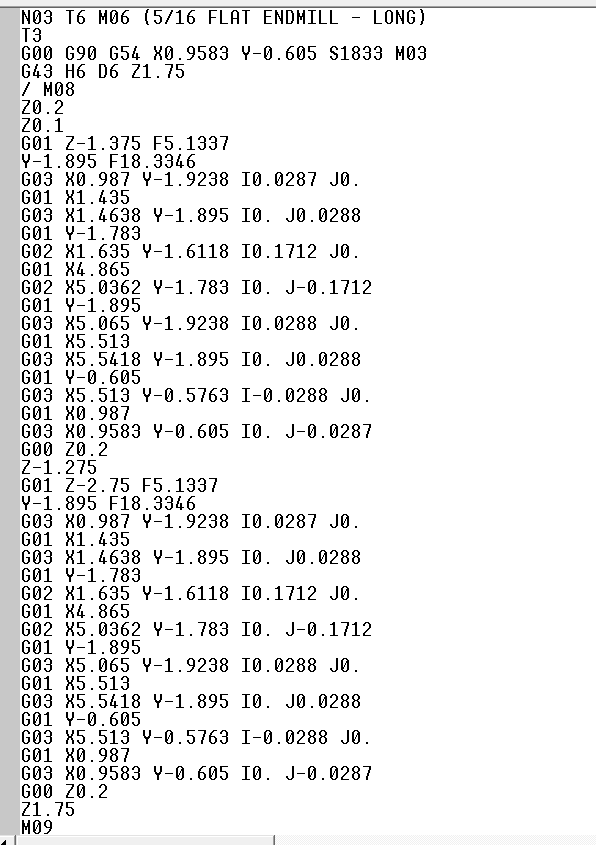
Found out the software won’t generate cutter comp when using a vertical plunge lead-in because of no XY axial move to initiate compensation.
3 Likes
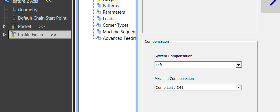
The reason you have no G41/G42 is because you have both the “System Compensation” and the “Machine Compensation” turned on.
the “System Compensation” offsets the tool by the radius of the tool, example, a 10mm tool will automatically be offset by 5mm from the selected contour, this means that the G Code is generated with the toolpath already offset ready to machine. So no G41/G42 is required for the machine to correctly cut the toolpath.
Now, if you want to be able to make adjusments at the machine control to adjust accuracy of cuts then the “Machine Compensation” is used which means that the G Code is generated with the center of the tool running exactly on the toolpath and then a G41/G42 will be generated in the code to tell the machine control that it has to do the Tool Diameter/Radius offset so you have to input the correct Tool dimensions in the CNC Machines Control.
So, if you want the G41/G42 then you set the “System Compensation” to OFF and just use the “Machine Compensation” G41/G42.
If you don`t want the G41/G42 then you set the “System Compensation” to either Left or Right and set the “Machine Compensation” to OFF.
Hope that helps 
Basically one does the compensation in the computer and the other does it at the CNC Machine Control !!
1 Like
actually not sure if this is right…i think the system comp just concerns the simulation…the machine comp generates the G41 or G42…but you do need an entry move to turn it on and an exit move to turn it off…because i usually run both set to left and i’ve had no issues
1 Like
It is correct, the System Compensation creates the toolpath at the radius of the tool away from a selected line and the Machine Compensation creates the toolpath exactly on the selected geometry.
Example, simple square block with the X/Y at X0 Y0, and you select the edge that runs in the Y with a 10mm dia tool, when you use the System Comp and post the code you will see that the X axis is at X-5 and if you use the Machine Comp then the X axis will be X0, see the Posted code below.
If you use both then the toolpath will be still offset by the 5mm but if the G41 is also present you should be then able to adjust for tool wear at the machine, so from what I can see then yes, you can use both but the system comp is not for the simulation, it creates the toolpath at a distance of the radius of the tool 
(TOOL #1 10. 10mm Flat EM)
N30 T1 M06
N40 G00 G90 G54 X-5. Y-5. S4000 M03
N50 G00 G43 H1 Z20. M08
N60 Z5.
N70 Z2.
N80 G01 Z-5. F584.2
N90 Y0. F1000.
N100 Y50.
N110 Y55.
N120 G00 Z5.
N130 Z20.
(NEXT CUT - SAME TOOL)
(Machine Setup - 1 Profile Finish)
(TEST CONTOUR CENTER G41)
N140 X0. Y-5. S4000
N150 Z5.
N160 Z2.
N170 G01 Z-5. F584.2
N180 G41 Y0. F1000.
N190 Y50.
Hope that helps to clarify it a little
1 Like