(Applicable to Standard 45 Degree Chamfers)
Often prints that are delivered using standard GD&T call out dimensions for Chamfers using a Diameter value and not a specific size.
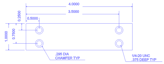
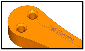
With the drawing above we have 4 holes that will be predrilled to a diameter of 0.201 for the ¼-20 tap and the chamfer diameter that is called for is defined as a 0.295 diameter.
In the BobCAD-CAM solid chamfer command the input asks for a chamfer value.
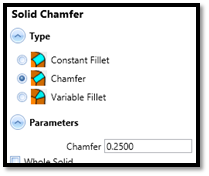
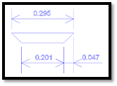
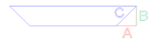
The input value that is being asked for is the distance across the face of the chamfer(The blue portion in the above image) The following steps walk you though exactly how to determine the correct value to input so that you can end up with the proper sized chamfer called for in the drawing.
Calculating the Chamfer
-
Take the size of the desired chamfer and subtract the size of the existing hole.
Desired Chamfer = .295
Existing Hole = .201
.295 - .201 = .094 -
Now divide the result by 2 to find the distance of just 1 side
.094 / 2 = .047
-
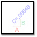
Now we need to find the distance of the chamfer face (Hypotenuse) of the triangle.
I. Using the formula A² + B² = C² we can solve and get the necessary value.
A² = .002209) + (B² = .002209) = C²
III. You get (.004418) = C²
IV. To find the result you use the Square Root function to convert to our value.
C = .06646
Taking the value found above you can enter this into the Chamfer field inside the Solid Chamfer command.
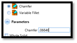
The result is a chamfer that is created .295 diameter as needed.