
Purpose: To explain how BobCAD-CAM software uses input geometry, and calculates thread height.
Input Geometry
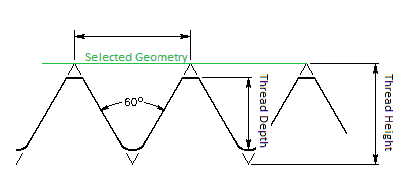
The input geometry you select in the software is used to define the Maximum Triangle Height (See Thread Image)
Example: Let’s say the customer is wanting to cut a 1”-8 diameter thread. Typically the selected geometry would be at 1” diameter. However, in real life conditions, you don’t typically start with a 1” diameter to cut a 1” thread, you would start with something that is turned to roughly 0.999” +0.005/-0.100 depending on the fit of the thread. This is the reason you see the difference in the above image between the Selected Geometry and the actual thread.
Thread Height
The Thread Height in the software is applied as the full triangle height of a given thread.
Due to different thread types and applications requiring different formulas to be applied the software uses a standard calculation to apply the entered thread height as the maximum triangle height as shown in the above image. It is the users responsibility to enter a Thread Height value that will result in the appropriate Thread Depth to be created for the users application.
The formula used by the software is:
Our formula is 0.5p/tan(a) or in another format, (0.5cot(a))/tpi
(a = half of thread angle)
The thread height calculated number as you can see does not factor in all the varieties of thread fit. It is intended to give a generic calculation based on the thread angle and theoretical points. For all the varying thread types and fits, it is very common to have to adjust this thread height to dial it in to the customers exact requirements.