
Hi @metal2cut,
sorry, I do not know, how I can help you further…
It’s getting too much for me, especially there seems to be some ambiguity in several places. And which program name or download should I give to you?
Harald
1 Like
Harald, the MillingGuy, many thanks!! You talk of “ambiguity in several places” sound like politics. I have 3 post processors that I am looking at, with the same part’s g-code saved from the 3 different Post processor, as to see and understand some of what controls what. 1 post processors is from you, the other are from my copy of BobCad, the generic 3 axis mill (BC 3X MILL) and the Fanuc (Fanuc OM BCPst) 3 axis mill.
What I also see is the only areas I need to look at is the very beginning, line 1 to line 15 and from line200 to 708. Not having pondered this just a few moments, it really appears the line 1 to line 15 are the most important. If you know, the only area I need to look at are from line ?? to line ??, this would give some me some confidence, w/o studying the whole post processor.
Use a text editor or Preditor Editor to make the changes and save .BCPst file, correct??
I will first try to run each program to see how far I get in the sample program.
Many, thanks, anything you or others can suggest is most appreciated!
I am praying that someone with knowledge about Post Processors will share just a small bit, please. Attached is a screenshot with the same sample program in all the examples. If you read across the top of each program is the name. Each has been saved using a different post processor, the post processor (from now on PP) is in each of the programs, but because limited to a few spaces to label what PP is being used this is the way there were saved: 0300 & 0500 used modified Fanuc MO; 200 & 400 used standard Fanuc MO; and 0100 used the Generic 3 axis mill.
You can tell the difference between the modified Fanuc MO and standard Fanuc MO by looking at line 17, and read the difference in 0100 and all the rest.
The Generic 3 axis mill 0100 program would not run.
The modified Fanuc MO 0300 & 0500 ran until line N05.
The standard Fanuc MO 0200 & 0400 would not run.
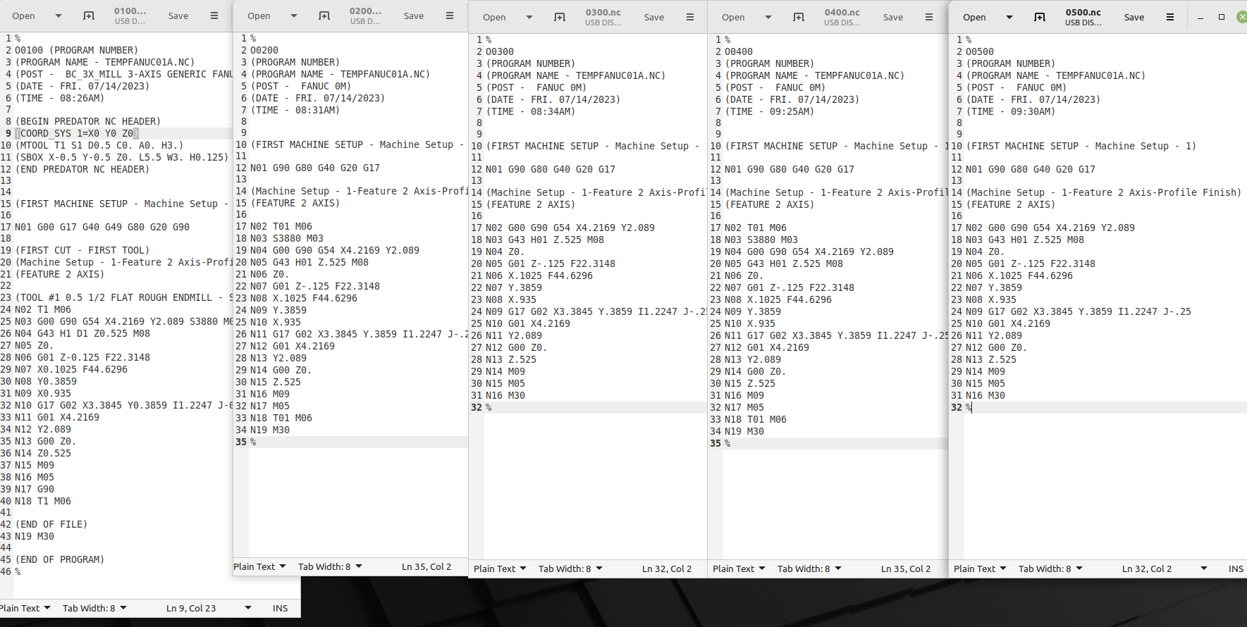
The sample part has a circular cut-out on 1 side of a rectangle. I do not believe it is recognizing this, I believe it goes to the next block in the program. If you push start more times it does nothing, the only way out is “reset”.
What am I looking for? I have had the PP open in a text editor, I am not shore if I will be allowed to save if I edit it, may need to use Predator Editor to save file.
Many thanks!
Metal to cut,
I am with David on this, It seems like 115 is an impossible feed rate in my experience.
Change the decimal to 11.5 and see what happens . If your calling a feed speed faster than the table rapid then it will probably just lock up. Steve
1 Like
Airnuts, the program below is what I just tried, it will stop online N05. You see the feed is slow, unless I have not followed your suggestion.
"%
O0501
(PROGRAM NUMBER)
(PROGRAM NAME - TEMPFANUC01A.NC)
(POST - FANUC 0M)
(DATE - FRI. 07/14/2023)
(TIME - 09:30AM)
(FIRST MACHINE SETUP - Machine Setup - 1)
N01 G90 G80 G40 G20 G17
(Machine Setup - 1-Feature 2 Axis-Profile Finish)
(FEATURE 2 AXIS)
N02 G00 G90 G54 X4.2169 Y2.089
N03 G43 H01 Z.525 M08
N04 Z0.
N05 G01 Z-.125 F2.23148
N06 X.1025 F4.46296
N07 Y.3859
N08 X.935
N09 G17 G02 X3.3845 Y.3859 I1.2247 J-.25
N10 G01 X4.2169
N11 Y2.089
N12 G00 Z0.
N13 Z.525
N14 M09
N15 M05
N16 M30
%
"
Many thanks!!
Hi,
- PP files are pure text files. Even if the file extension is BCPst (BobCamPost), they are pure text files.
Text files can be opened, edited and saved with text editor programs. Regardless which editor you use, the saved content will always be the same as editors just save the text as it is. If an editor supports syntax highlighting (different text colors, font style) this is just a help for better visualization.
So yes, you @metal2cut can save the file with your editor, do not need Predator Editor, but can also use it, if you like.
And regardless which editor you use: if you save the PP file, BC will use this already on the next ‘Post’ or ‘Post & Save As’ action to generate the G-Code file. - why don’t you follow my suggestion to edit/play around with G- and M-codes. You can do it even with your not working g-code? Just use a text editor as G-Code also is just plain text. Make your desired changes, save it, load the G-Code into your system and check how it behaves. Do this over and over again making small changes until you figure out, where the problem is. Then you can go for the PP to correct it.
When the chaos is sorted out, further help can be given.
Bye, Harald
1 Like
Hello Metal2Cut,
As Harold has pointed out the post processor files (.bcpst) are just ASCII text files. The only precaution when modifying them is to not use a document editor like “MS Word” as it will add formatting to the file which will not make it work. We recommend “Predator”, Notepad, or Notepad ++(Free editor).
For the post processor modifications. Really it needs to be determine exactly what the issue is first. It is not efficient to trouble shoot a machine run issue by modifying the post processor itself. It is best to modify the Gcode program by hand, and then once the problem is recognized and the solution found, the post can be modified to work in the necessary way.
There are many questions your thread has left out. Here are a few to help you along:
- Does this machine have a tool changer?
- Do you have any NC programs that are stored in the machine that do run ok?
For learning more about post processor editing and modification you can utilize a few existing resources:
Link to Online Post Processor Help System - This includes some tutorials you can use to learn the basics of post modification. https://bobcad.com/components/webhelp/PostProcessorHelpSystemFiles/Welcome.html
LaunchPad Guided Post Learning - https://launchpad.bobcad.com/bundles/post-processor-machine-definition-bundle
Hope this helps (HTH)
Alex
1 Like
Harald, Many, many thanks!
This is how I have started, attached are 3 pages in 1 pic, of the 15 total that I believe show (in the red circle
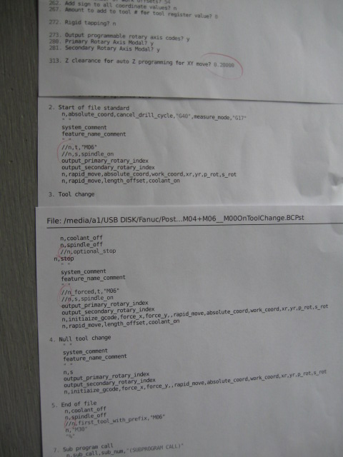
) your edit “//n,t, “M06” under #2. Start of file standard” in the post processor (PP). Specifically, the “//” at the beginning of the line as to not be included/used in the PP. When you view pic the top shows (z clearance = .200") line #313 (to keep to 1 pic) I show this out of order. I want to control the variable in the BobCad software, so I set like the others to 0.0.
The changes I have made are as follows:
#204 from NO to Yes
#206 from NO to Yes
#313 from 0.200 to 0.0
#513 from NO to Yes
Should I attach the total 15 pages of PP, so it can be viewed?
These were changed 1 at a time, with a new program each time. Do I need to reboot the PC, if I edit the PP in the PC? I have original PP is saved on thumb drive.
I printed out the 15 pages, so I could write down the changes as I go. When I look at the lines you edited, I can see some connection, but I am not understanding what to look for in the currently stops on line 04. Even if you look at the line before, I don’t see anything obvious.
This is the most recent sample program, it stops on line 04:
"
%
O4445
(PROGRAM NUMBER)
(PROGRAM NAME - TEMPFANUC01A.NC)
(POST - FANUC 0M)
(DATE - SUN. 07/16/2023)
(TIME - 11:39AM)
(FIRST MACHINE SETUP - Machine Setup - 1)
N01 G90 G80 G40 G20 G17
(Machine Setup - 1-Feature 2 Axis-Profile Finish)
(FEATURE 2 AXIS)
N02 G00 G90 G54 X4.2794 Y2.1515
N03 G43 H01 Z0. M08
N04 G01 X.04 F4.1253
N05 Y.3234
N06 X.9871
N07 G17 G02 X3.3323 Y.3234 I1.1726 J-.1875
N08 G01 X4.2794
N09 Y2.1515
N10 M09
N11 M05
N12 M30
%
"
There is a screen in BobCad, Data-Cam Tree Manager that allows x, y, & z work offset, clearance plane, it reads to me like you could use the G54 data in this area, but not both (G54 in the mill & this option). So currently only use G54 in the mill, but willing to try.
Many thanks, all suggestions welcomed!
Alex, just saw your suggestions, many thanks!
Yes there is a tool changer, umbrella type 20 position, but do not plan to use. I need the 220v hi-speed spindle attached to BT-40 spindle (with bolts, so no air required), this is a dedicated application.
When I acquired the mill, parameters were lost, no programs that I have found to work after parameters and diagnostic were re-installed. Prior to just recently the diagnostic data was outdated, and I was unaware, currently I have been in contact with the machine builder to insure all parameters and diagnostics are correct.
I will be following up on the tutorial links you attached, many thanks.
Hi @metal2cut,
you’re pretty resistant to suggestions, aren’t you?
Again: follow the recommendations that have now also been given to you by Alex: work directly on a (new or existing) G-code and make this run as you would like to have it. Then it is possible to focus PP tasks.
Bye, Harald
1 Like
Harald and Alex, many thanks.
When I read your suggestion about editing (as to remove the lines of the part program that will not work) the G-code of the part, that this is the process to developing a Post Processor that works, it did not sink in my brain, this is what I can offer. I am committed to finding a way to make this mill work, if it will only will do the profile and pocket with a ruffing tool and cut & finish tool and finish cut, with a way to set the next tool.
As to make shore, I get this correct, start with the sample program (set this sample program up to run the part in BobCad) use G54 on mill for “machine offset”, no tool length set, do not use tool length in BobCad, no tool offsets. I have read about the “debug” on Block 26, still got more to read, thanks.
The current sample program is only a profile 1 time around, without finish cut. Is it ok to start with just a simple profile vs. pocket, no drill cycle stuff?
When creating this sample program, use the standard Fanuc OM PP option and use this as the starting point?
I am very grateful for the help, all suggestions are welcomed, many thanks!
I wanted to share this link for those that are new to Gcode programing and understanding what all the codes mean and how they work. This book is very valuable, especially for Fanuc style code.
https://www.amazon.com/Programming-Handbook-Third-Peter-Smid/dp/0831133473
HTH
Alex
1 Like
- do you have a working G-codes for your machine
- can you do your entire workflow with single g-codes running one after the other?
bye, Harald
1 Like
Harald, I would not be able to say with confidence that I do, because I have only gotten to through the very beginning of the programs. The mill has run programs (need to quality, simple easy program), but not after the new diagnostic up-date. The modified PP you sent (the 2nd one that allowed tool change) seemed to work, all axis moved in a simple program like I have been working with. I may reach out to the machine builder with this issue.
Thanks!
@metal2cut: that was not the question.
You want to make a product. So you need to know the individual steps to achieve your goal.
You want to make the product with a milling machine. So you need to know the individual steps you want the machine to perform to get the piece of your dreams. For that to work, you plan the machining work steps like:
- mill facing with tool d=10mm
- do contour milling with same tool
- drilling holes with drill tool d=5mm
- make pockets first roughing with tool d=6mm
- make finish with tool d=4mm
So as you have BobCAM, you can build all those operations. But as you do not have the proper PP you cannot generate the G-Code also. So take a PP that is closed usable. For each operation generate a separate G-Code file. Load each one step by step into you machine and check, if it runs the way it should. If you come to a problem, direct fix it in the G-Code (using Alex book reference will sure help).
If then all G-Code files work as expected, put them together in one G-Code file. Between each G-Code section add those operation you want the machine to do automatically for you (= replace your manual tasks done before between each G-Code file).
If the whole G-Code is doing like you want, let BobCAM generate a single G-Code file and check the difference to your hand written G-Code. Then you can figure out the differences and adapt the PP to work the way you need it.
Good luck, Harald
1 Like
Not seeing any reference to a Tool # in your G Code, I used to own an old Bridgport 412 3 axis mill that used Fanuc 0M-F and I always needed to “call” the tool # in the code in order for the Fanuc to look for and execute the G43 Z** H** line of code, if you have set your “speeder” as tool #1 then to call the H1 you need the T1 in the code.
That worked for me OK years ago and my Fanuc was 0M-F, check what version of Fanuc your machine has as the Parameters may not be set correctly to allow the G Code to run as you are trying to use it.
May help, may not, it worked here.
1 Like
I would start by looking at the beginning of the diagnostics page. Most Fanuc controls made in the last 20 years start the diagnostics with, “Why am I not moving?” If you press SYSTEM until the parameters are shown, the diagnostics tab should be immediately after the parameters. The first few diagnostic items should have values of 0 or 1. They will be things like Feedrate 0%, waiting for interlock, waiting for FIN, axis not enabled (servo off), etc. Hopefully, that will give you a clue as to why you are not moving. Do you know what model 0 you have? Is it a 0C, 0D, 0i, etc.? If it is a 0i, there should be an extension on that as well such as 0iD, 0iF.
1 Like
hey
why is the G17 so late in the program
I have that in the same line with G43 etc should be modal but…
MillingGuy (Harald), Many thanks for your help!
general, From what I have read & seen about “parameters” and “diagnostic” areas of the controller, the ability to have 2 mills in the shop, with the exact same model of controller on each, and they possibly could have some significant differences in how they operate. It only takes 1 of those “bits” to be a “0” vs. a “1” to make a change.
Cabinetmaker, I started with the manuals that came with the mill, only to find that there was an up-dated list of “diagnostic” data that matched the “parameters” that I only found out recently by reaching out to the machine builder. The machine builder I have been working with, has been excellent, and I pray we will prevail, and the mill will accept g-code properly soon.
Just a short note about the direction how things are going, The machine builder has help enormously, starting with those fussy “diagnostic” settings.
We are working on the ATC to make it function completely proper with the correct setting on the Z axis location in “diagnostic” to confirm X20.6 is a 1 when in MDI keyed in; G91G30Z0.; that the head stops to make the “1” confirmed, at the location (+ - z) to accept toolholder from tool changer. Apparently, it’s necessary for the ATC functioning properly, so not having an error starting with the ATC. This is where I am at, just moved the “switch dog” to set that.
As for a Post processor, the machine tool builder told me, this mill can be used to “broach” using the “Z” axis, and my hope is there may be an existing PP to use.
Many, many thanks!!
[Solved] This was solved by starting with the machine builder and get the current MATCHING (this is critical) parameters, diagnostic & ATC macro all need to match. This will allow all to work properly together! Many thanks!!