
I f you got a tool changer on the mill, you might want to delete the M06 too
1 Like
PJK, many thanks, good thinking!! I will do that even though the air will be disconnected, my tool changer is the umbrella style, it uses air to move toward the spindle.
As to be clear, I used the “find (MO3, MO4, MO6) and replace=M05” in Predator Editor after the post processor change in BobCad, (as per MillingGuy’s suggestion).
From “MillingGuy” in earlier post M3, M4, and M03 and M04 are not the same and need to be search for as well, separately?
The is from my earlier post:
"I have received this suggestion to start the CNC G-code file with something like this:
N10 G90
N20 G10 P1 X-12.5000 Y-8.000 Z-12.0000 (P1 -Set the Datum of G54 )
G54 (G54 work offset active)
Here Your program goes
.
.
.
I understand that the “machine location” will be used with this suggestion shown above. I am looking for a way to make the path to get usable g-code to the mill with as few steps as possible. I need to understand what I can automate (not really) but make it as easy as I can for myself. I am searching for suggestions around this.
Many thanks
Edit: I have “machine motion” by command!! It ran for a while 15 minutes and received a Fanuc alarm 008 that says that a M02 M30 or M99 was needed in the program. Apparently too good of a job removing M0 from the program. I did not use the “check” button on the control, but will next time.
Many thanks!
In Predator Editor, I have found the edit machine template (3AXVMILL); I unchecked the “Tool Change M6” and unchecked program numbers, to conserve memory in mill. This first attempt did not take out the M6 or program numbers (the numbers I want out are at the begging of each line, (line & block are 1 and the same, correct?))
The only way so far is to use 'find & replace = M5" using Predator Editor.
If there is a better way, now is the time to share the secret handshake!!
Many thanks!
@metal2cut
I’m sorry, I can’t keep up with what you’re trying to do. Originally understood that your milling spindle should not rotate. In regular machines work like this:
M3/M03 … turn spindle clockwise
M4/M04 … turn spindel counterclockwise
M5/M05 … stop turning spindle
M6/M06 … insert new tool
M7/M07 … mist coolant on
M8/M08 … flood coolant on
M9/M09 … mist and flood coolant off
Finally, it is the postprocessor used that determines how the G-code is generated. So you have to find out which PP BobCAM uses in your case and adjust it so that no M3 or M4 (M03/M04) instruction is generated.
Regards, Harald
1 Like
MillingGuy, thank you, I will need to edit the g code every time, or I need to “adjust it so that no M3 or M4 (M03/M04) instruction is generated.”
I read this, and it sounds like a special post processor for my situation would be the ideal solution. Did I read and understood this correctly? If so, is there any suggested reading I should look at? I will be using this set-up (the PP to remove spindle commands) for this ongoing application. I am interested in creating a new PP if this is possible and will speed and have a higher degree of safety & accuracy, hopefully the program will be ready w/o any more editing program manually. The mill is a bed mill style, with axis travel 25"x16"x24", no ATC.
Any help in, creating a post processor for this application would be warmly welcomed, many thanks!
Hi,
upload the PP you are using. It is just a text file with extension *.BCPst. Then we can try to do the next step. You can find your used PP here:
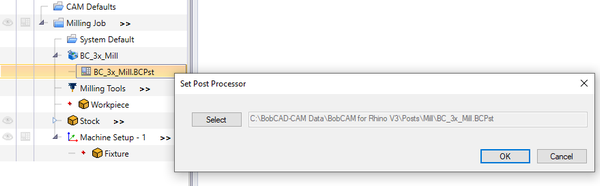
Note: this is just an example, if I use BobCad default BC_3x_Mill machine that uses by default the BC_3x_Mill.BCPst postprocessor
Regards, Harald
MillingGuy, From your earlier suggestion, I am using the “3AXVMILL PP” from the screen you show in the above thread. Then I would use Predator Editor to “find & replace” the MO3, MO4 & MO6 are replaced by MO5. This PP is the only PP that I have tried, and allowed the mill move, there could be other PP that will work, for example the FanucOM.BCPst is the only Fanuc PP listed. The controller is a 1995 (B) Fanuc OM. I am open to suggestions, if one PP is easier to tweak than the other.
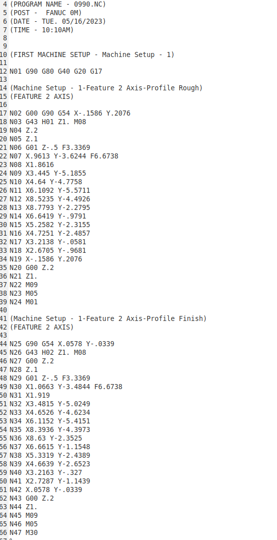
This is the PP I used:
See next post for the proper Fanuc OM PP.
I think this has copied correctly, if not I will try again!
Many thanks!!
@metal2cut my example was just an example. I do not know, what PP you are using, but you can figure it out going the way I did…
You have to sent/upload you PP file. BC_3x_Mill.BCPst is just one of many other PP files out there when you install BobCam. And BC_3x_Mill is a generic one from BC that can be used as a starting point if no other PP file do the job for ones machine.
Bye, Harald
MillingGuy, many thanks!! I have a sample program that I used this PP with, and just ran it & it ran ok, just seems best to start with a PP that is best suited for the controller, PP is attached.
I will need to pause some programs to install the next tool, and “touch off” for the Z axis.
This is the PP, for Fanuc OM:
Fanuc0M.BCPst (27.2 KB)
Many, many thanks!
Hi,
check Fanuc0M_NoM03+M04+M06.BCPst (27.2 KB) instead your FanucoM.BCPst. The PP now does not output a M3 or M4. I also kicked M6 as it might not be useful in your case without turning the spindle 
Bye, Harald
MillingGuy, thank you!!! This worked well, my sample program is profile & pocket commands, I just did not think to include any hole pattern. Before I tried at the mill I used the “find & replace” the MO3, MO4 & MO6 to see if any were found, naturally none were found, worked perfect. I did not try any tool changes, like to ruff vs. finish tool, in sample program, but will tomorrow.
MillingGuy, many, many thanks for hanging in there with me, I am so grateful!!
MillingGuy, many thanks for your help. I have a sample program, 2D profile with a ruffing end mill 1/2" dia and finish pass end mill 1/4" dia in BobCad, the g-code has a MO9, MO5 & MO1 at the end of ruffing cut, but does not stop for tool change. It does recognize the M09, because I see and hear the light & relay for the coolant pump go on, even though there is no pump connected.
I heard that I may use something like the pump relay to control (with additional relay) the hi-speed spindle off/on. But still need to stop program, to change the tool and then “touch off” with a new tool.
Am I correct, I will use the G 54 as the area, of the Fanuc control to change the z axis data that matches the tool change?
Many thanks!
Hi,
I didn’t change M7, M8 and M9 directives so it is normal that if you use coolant with your tool the system generates M7 or M8. As M9 turns off coolant it is no problem when it is used although no coolant activation was done before.
As for the rest I do not know something about Fanuc controller nor do I know your machine.
G54 just tells the controller which workpiece offset the machine should use. G54 is the first one followed by G55, G56, …
Bye, Harald
MillingGuy, thanks for your help! The response below was suggested for the situation I am describing.
“A good code to use for stopping the machine so you can change the tool would be M00. This is a Mandatory Stop. Meaning it doesn’t need any buttons pushed on the control for it to work. M01 if used, needs the Optional Stop Button on to work.”
You have sent PP that uses MO1, can you tweak the PP, so it will use MO0 or I need how to use MO1, correctly, is there something I need to look for to make MO1 work?
MillingGuy, thank you so very much!
@metal2cut when do you want the machine to stop? Easiest way to do it automatically is when you make a tool change within BC. The PP can be modified that way doing a M0 instead of M6. Should it go that way?
Bye, Harald
MillingGuy, this attached file is the sample test file, it has MO1, I think I need MO0 to work proper.
Many thanks!
Harald (The Wizard!!) aka, MillingGuy, you have been extremely helpful, I can’t thank you enough!! This PP worked just the way it needs to, stops at the tool change, I used “handle mode” to move z axis (as if a tool change & touch off, occurred) then back to “start cycle” and it finished the program.
When a tool change is required (I need to understand the “relative screen z value” before & after to use this as the value? Correct) & the z axis in G54 requires an update, because of the difference between the 1st & 2nd tool, z value? Or is there a different way? I will not be using pre-set tools in toolholders, I will be using collets that have no stop on the z variable to make the same z height for both tools.
What I am asking about is the process, so I know what the value (number) is, and from what position (DRO) screen, the “relative” (not the machine position or absolute position) position is the number to write down and insert in to the G54 z value, or do I use the before and after position (the difference) and do the subtraction or addition (the about the 1st tool was different height (+ or -) than the 2nd tool), and use this in G54? Just need some clarification, I have seen YouTube of this, but was a newer Fanuc controller, so it was not completely clear what the number represents. My controller is Fanuc OM.
Harald many thanks!!
I will use the “solution” button soon.
@metal2cut sorry, from sentence “I used “handle mode” to move z axis…” on I can no longer follow what you are meaning and what you want to archive.
I still do not know something about Fanuc or its controller(s) therefor have no knowledge how the machine and controlling unit behaves.
Bye, Harald
1 Like
MillingGuy, thank you so very much!!! The tool and work offset is specific to the mill, I completely understand. I believe the solution is a few threads up, I checked it off.
Many thanks for your help, Harald (The Wizard!!) aka, MillingGuy!!!