Post Processor for Fanuc OM mill, needs a small edit

Post Processor for Fanuc OM mill, needs a small edit, so program is complete and ready to run parts.
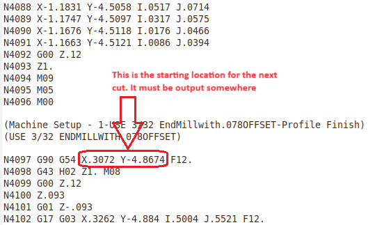
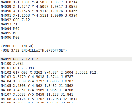
This pic shows what a similar program looks like. Need line 4097 & 4098 edited out and add “F12.” at end of line 4099 when finished.
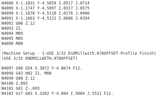
 Line4098G-Code

Like this:
LINE 97 & 98 REMOVED

The area of the program is at tool change, the attached pic is the area in question. I have in “debug” mode.
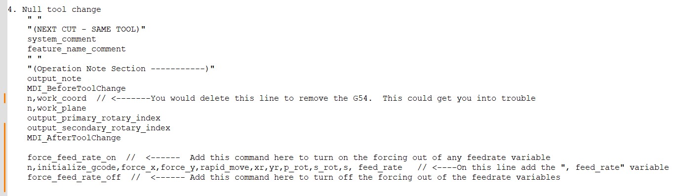
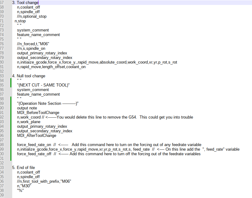
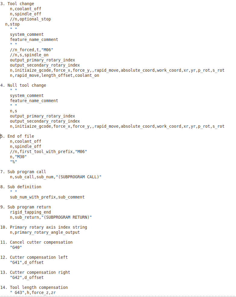
Also attached is the area of the Post Processor (PP from now on) that references lines 3 and 14.

I have found some information that shows my early post needs more information to understand what is occurring in the background, and that is to set line 26 to yes in the Post Processor “debug” so additional data is displayed.

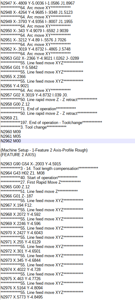
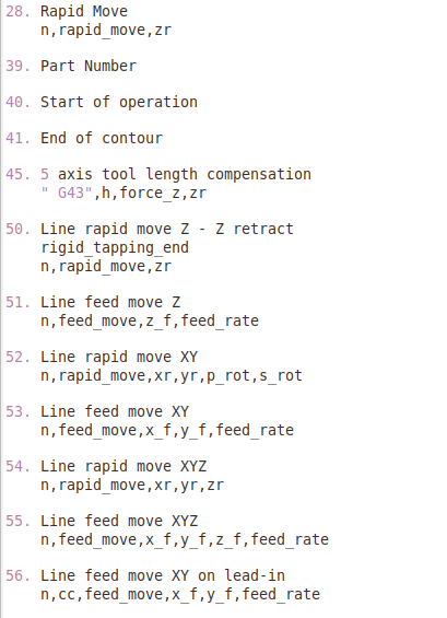
There are nested areas that have more than 1 number that hint at what is controlling that line of code. Like in the following:
"
N2963 G90 G54 X-.2003 Y-4.5915
3 - 14. Tool length compensation
N2964 G43 H02 Z1. M08
40. Start of operation
"

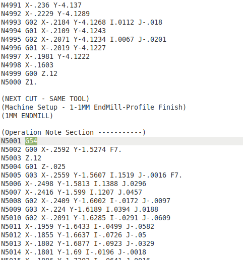
The line with the *********s show what is going on in the background for line N2964 the (3 - 14. Tool length compensation) is being referenced. The attached pic (PostP_D Bug line 2963) shows the code in the rest of the program. The other pic (PostP line 3 to 14) is line 3 to 14 of the Post Processor, with the description of what line 3 does and what line 14 does.

The application has a hi-speed 220v (spindle with collets) bolted to the Bt-40 spindle, no ATC will be used, I plan to “touch off” and set the “tool offset” each time there is a tool change. I have asked the machine builder about this application, his response was that it was like a broaching application, don’t want the BT-40 spindle to move, but need all the other feathers to work. Parameter 024.2 = 0, (this does not check the RPM of BT-40 spindle to see if up to speed before feed will start) is the only parameter that required a change.

If the complete PP needs to be attached, say so. I pray that this is written well enough to understand what edit to PP is required.

Many thanks in advance, all suggestions warmly welcomed!

Edit: What about a “Null tool change” (change from 3 to 4 in PP)?

After re-reading number 4 “Null tool change” and reading some of the BobCad Lessons this is my belief that this is the area of the Post Processor (PP from now on) that needs to be edited.

I need a 2nd opinion, or I need to edit each program and cut parts like I have been doing. Naturally my hope this edit will make the program consistent and the parts more uniform.

Many thanks in advance, all suggestions warmly welcomed.

Hello metal2cut,

Your request is a bit confusing IF I am reading it correctly.

One confusion I have is that in your corrected code you have removed the next XY location from the null toolchange completely. This XY location must be called up somewhere so the machine moves to the correct location prior to plunging in. If you are expecting to manually position the machine to the starting location, then execute the cut a much deeper conversion must be had to ensure the output from the post processor will be correct and not cause crashing/issues at the machine.

Some combination of how the operation is programmed as well as maybe using a G92 to set the current (manually positioned) location as zero would be necessary in my quick thought about it.

The position I am referring to is:
image

Alex

1 Like

Alex, bless you for considering the situation. I have several parts on the way to final cut and cutting parts now. To do this, I have been editing out the part of the program what caused issues and have found that only the “G54” (in line N4097) needs to be removed, but a feed was needed several times, so I just add an “F12.” to that line every time, it may not always require it.
In the same area of program, I also remove the “Z1.” (line N4093) so the Z axis just moves between -.093 & .120". This seems to be all that is needed.
I hope to finish my parts soon (the machine work part) & then will work this full time if needed.

Many thanks!! All suggestions warmly welcomed.

Here is a quick example of what you can do to the post processor. Please note that if you remove the output of the G54 that comes from the work_coord variable in the post null toolchange postblock you could later run into issues.

If you use this post to generate a program where you DO use multiple work offsets and you happen to change work offsets while using the same tool then the code would NOT be in the NC file thus causing your machine to cut incorrectly. You have been warned so to speak :wink:

Here is some notes on how I modified the BC_3x_Mill.BCPst post processor to do what I believe you are looking for.

HTH

Alex

1 Like

Alex, bless you!!! I will try this, but I may wait until I get my current parts out the door. Your comment & suggestions look very promising, many thanks!

Alex, many thanks! I have edited the post processor as per your suggestion, please see attached pic. I usually save each part program with only 1 tool size per program & only a single work offset. Soon I will test this new post processor, when I do, I will review the g-code (like I do now, looking for Z 1.0 & G54).

Is there anything else I should keep an eye out for? Many, many thanks!

Not thinking of anything at the moment.

Alex

1 Like

Alax, many thanks for your help!! Please work me in when you can. Bless you! The pic shows a similar program to the example with the “null tool change” edits to post processor as you suggested. My concern I am trying to explain, you may very well have explained completely, it could be me not understanding completely, but the pic shows G54 & Z1. (N5000 & N5001), are still in program, several places. Can I get program without lines G54 & Z1.? The parts I cut are delivered, so I have time for this post processor now.
If I run the program as shown, the Z axis would go to the “home” location for no reason. I edit each program now so it does not happen. If this is how it needs to be, please say that. Many thanks

First: Why does recalling the WPC cause a problem? It may be necessary or may not need be in some cases but it is safe to remain. Easy to remove in most places just remove where it says work_coord in the tool change area being used.

Second: The output for feedrate is normally on the G01 line not a G00 line as that is where it is used. You can set the feedrate at any location before the feedrate is required but G00 is rapid and does not use it.

Third: the Z1. move is the clearance plane move in your operation or the fixture clearance move set to clear clamping. If you really want to remove it you can but you could consider looking at your settings in the program. If you really want to remove the output then you need to look at the post in section 50.

1 Like

twjones1966, many thanks, & happy new year, I am ever so grateful for your help. I use the clearance plane set to the application/project, this only needs .120" (total .12 + .025 deep cut, is all the z action required) and to have the z axis go all the way to its highest position (like -14") seems like a lot of motion for no reason. This project has a small x, y, footprint (4" x 6") for the tool and is always pocket operations followed by a finish cuts around the perimeter with small tool .032".

Currently, I save each g-code program for 1 tool with the matching tool offset & 1 machine offset for that 1 part, spindle & tool setup. So, usually 1 ruffing program with larger tool and 1 finish program, with smaller tool and touch off using z axis for each tool offset before starting each part of the job.

But I have a 2nd spindle (plan to use a 2nd work off set with this) that I plan to mount soon and will use 1 spindle for ruff-cut and a 2nd spindle with the finish tool set up, with a 2nd tool offset.

The addition of needing an output for feed rate, this was flagged every time earlier (when I really needed to get the parts cut & do the finishing operation to get them out the door) in simulation/test of g-code. I got familiar & quick with manually editing the program, this feed rate that I edited, may not be needed or properly located in the later programs.

twjones1966, bless you, I will study my post processor, looking for the following areas as per your suggestions:
“work_coord in the tool change area being used”
“the post in section 50”

If this editing of the program is something that can be made to work automatically, with some adjusting of the post processor, I will do what I can to fix this.

Many thanks

twjones1966, bless you! We had some high wind here & needed to pic up the yard. I have studied the post processor (PP) and attached a pic, so I am clear what area of the PP needs editing & exactly what needs tweaking.

Below is from my 2 Nov’23 post, above. Showing line 3 (work_coord) of PP toward the bottom:
This before the edit:

“n,initiaize_gcode,force_x,force_y,rapid_move,absolute_coord,work_coord,xr,yr,p_rot,s_rot”
This is after the edit:
“n,initiaize_gcode,force_x,force_y,rapid_move,xr,yr,p_rot,s_rot”

The attached pic shows line 50:

This before the edit:

“50. Line rapid move Z - Z retract
rigid_tapping_end
n,rapid_move,zr”

This after the edit:

  1. (remove all of this command/statement?)

Please review, is this what is needed?
Many thanks