Im new to the millturn software (version33) only been messing with it for a few days, but im trying to call the subspindle (Haas ST20Y) to grab the part pull it to do some milling, knurling and OD turning while its being held by both the main and sub spindle together. Im trying to call the subspindle in the MDI page after the last operation but it only gives me 1 category to fill in a travel distance and thats it. How would i go about doing this? and subsequently how would programing operations while the part is being held by both spindles work?
1 Like
Hello Marco,
You can look at the saved MDI functions for the Cutoff Transfer and see the MDI sequence that has been created there.
Basically with MDI you will need to manually build the output you need to be output before and/or after the operation.
If you wanted to say turn a part while both spindles are holding the part you would need to create a turning operation. Then in the MDI Before section you would need to add the commands to open the sub spindle, move over and grab the part, then spin up…Then in the After operation you would put in the codes to let go of the part and return the sub spindle to it’s resting position.
Hopefully this makes sense.
Hey Alex, i have managed to MDI the part transfer and everything goes well while machining, the only thing is that during simulation it always simulates the sub inside the chuck LOL. I Know its because i use the machine coordinates to move the sub to pick up and pull locations, this is my Post i made
G54 G00 B-20.5 ( RAPID SUB TO CLEARANCE)
N128 M111 ( SUB UNCLAMP)
N129 G199 ( SPINDLES SYNC)
N130 M12 ( MAIN SPINDLE AIR BLAST)
N131 M112 ( SUB SPINDLE AIR BLAST)
N132 G97 P100 M03 ( MAIN SPIDLE 100RPM)
N133 G04 P2. ( DWELL 2 SECONDS)
N134 M13 ( MAIN SPINDLE AIRBLAST OFF)
N135 M113 ( SUB SPINDLE AIRBLAST OFF)
N136 G00 G54 B-23.5 ( SUB SPINDLE TO FRONT OF PART)
N137 G01 G54 G98 B-25.25 F35. ( SUB SPINDLE TO PICK UP PART)
N138 M110 ( CLAMP SUB SPINDLE JAWS)
N139 G04 P1. ( DWELL 1 SECOND)
N140 M11 ( UNCLAMP MAIN SPINDLE)
N141 G04 P1. ( DWELL 1 SECOND)
N142 G01 B-15.625 ( SUB SPINDLE PULL PART TO NEW LOCATION)
N143 M10 ( MAIN SPINDLE CLAMP)
I use G55 after the part pull to program the rest of operations. Like i said the program runs fine but i was just wondering what i have to do to make the simulation run better?
Hello,
To get the simulation to show correct I am thinking you are missing the call to use machine coordinates vs using your work offset coordinates. Put the machine coordinate output call in there and that should work
HTH
Alex
Awesome that seemed to work thanks Alex! also just as a extra i know this is nitpicking but how could i fix the sub spindle simulation where the jaws on it are the right size. My sub spindle is using 1in jaws, the sub on the simulation seems to be bigger so its covering more material than it should be
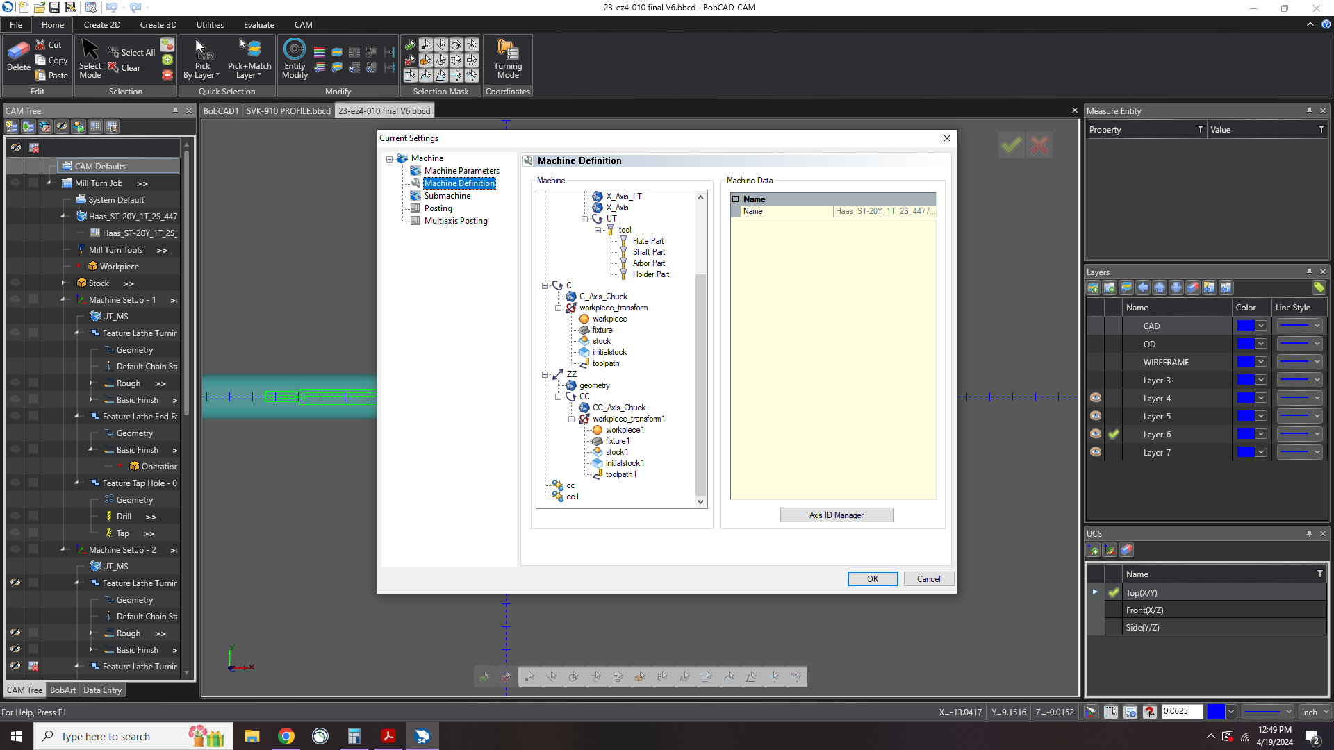
In the machine definition (Edit through current settings) you can modify the sub spindle chuck. In that dialog you can modify the parameters for the Jaws.
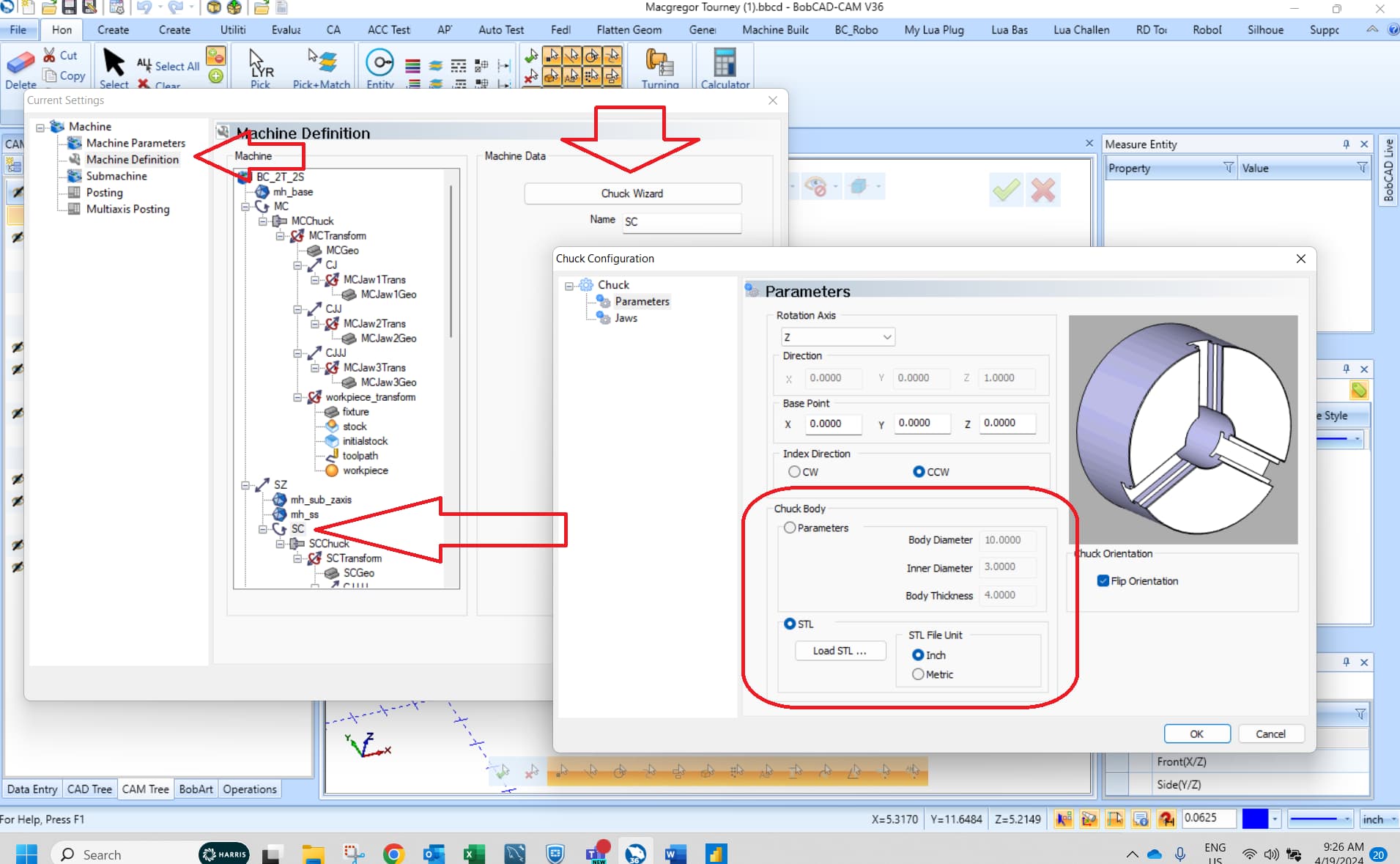
HTH
Alex