Thoughts about Tabs (= bars preventing a fly away)

Hi All,

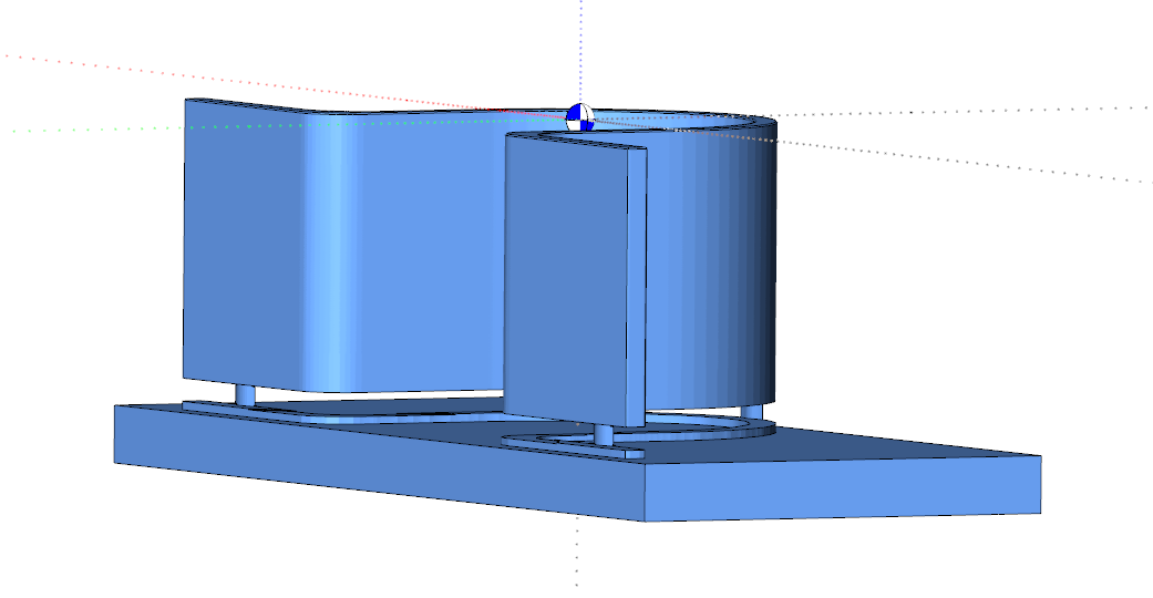
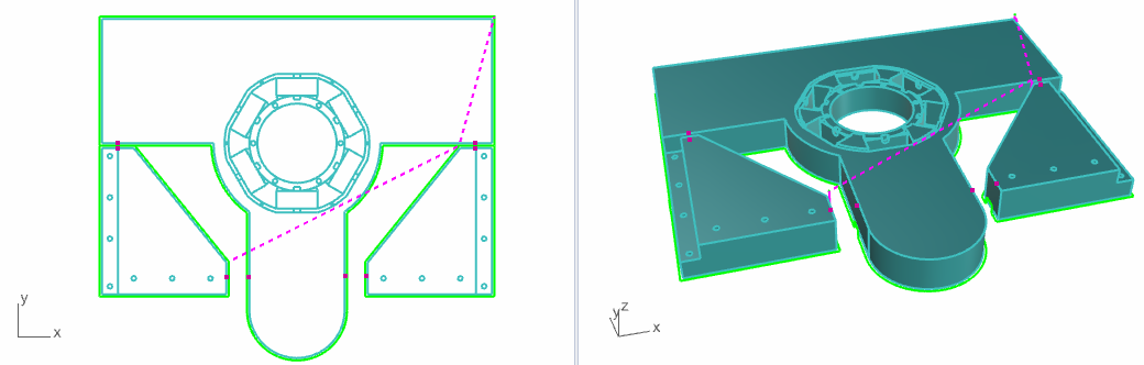
due to a customer’s request with special needs I took a closer look at the topic of Tabs. Here is the geometry I experimented with:

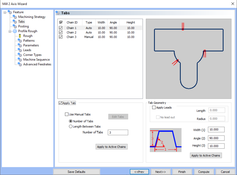
Dividing the Tabs in Chains is a clever approach. It lets you assigns Tabs for each chain, but for whatever reason one decide not to use it, it’s easy to deactivate it without loosing already set Tabs.

On the other side, this separation makes it impossible to assign Manual Tabs in just one step. Having three Chains, you must select each Chain and go the way via ‘Edit Tabs’.

‘Edit Tabs’ always starts to place the amount of Tabs given in the field ‘Number of Tabs’. Sadly it does not take care about ‘Number of Tabs’ = 0, where it still place at least one Tab on the chain :frowning: Thus the system cannot be tricked with it and I miss very much a “Clear all Tabs” button.

Automatic setting of Tabs is a good invention.


But it suffers from the selected positions or possible options. Tabs have to be removed manually when the pieces gets off the machine. Position on curves and corners are more worse to work as straight areas. So in many cases, users still have to use the ‘Edit Tabs’ button and replace the Tabs.

I didn’t check how easy it is in native BC-CAM to remove an automatic set Tab. In BC4Rhino it can often just be done with zooming to death to get the pink square.
image
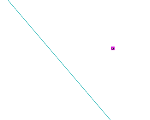
Otherwise you set and set and set Tabs…
image
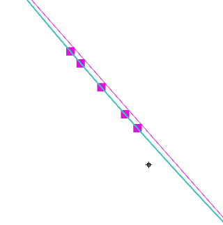
Again: a ‘Clear All Tabs’ button will help out of this with elegance.

I also didn’t get the key, when doing a ‘Edit Tabs’ on e.g. “Chain 1” coming back to the Wizard the last Chain gets selected. Disturbs the workflow, especially if the same Chain has to be processed again.

As told before, each Chain must be handled on its own.


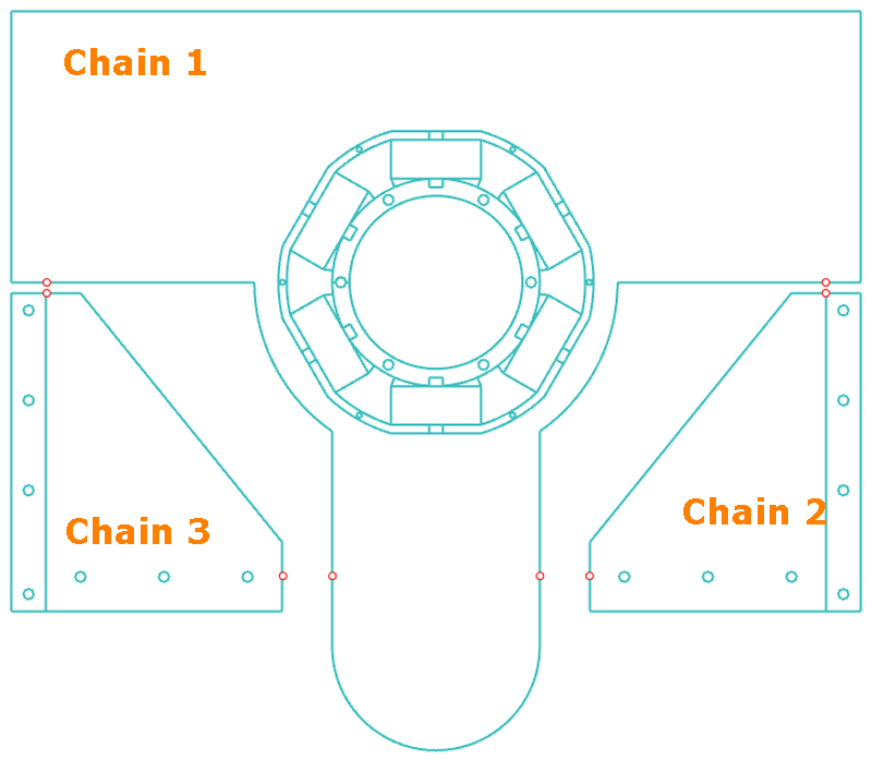
In regular, parts will be placed very close to each other (keyword Nesting) having such space the tool can go through them. Placing Tabs on each Chain on its own makes it difficult to position pairs that belong to each other (see above image the red Points. And all of us know, that a minor shift of two related Tabs will cause to have just a half or no Tab at all during the mill process (milling Chian 1 destroys Tab from Chain 2 and Chain 3, Chain 2 destroy Tab from Chain 1, …) and the parts might fly away.
Coming up with this what do you think about an improvement to let the system set Tabs by selecting points the user has placed?

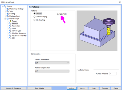
I was also looking for quite a long time, why ‘Generate Toolpath’ didn’t generate the Tabs. You should know: I love the pattern ‘Contour Ramping’. But Tabs are just supported for ‘Standard’ pattern :frowning:
image

image

image

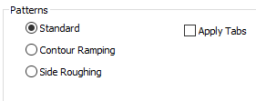
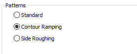
Wish: Tabs for all patterns, at least ‘Contour Ramping’ :wink:

The ‘Apply Tabs’ checkbox in the patterns view is unfortunate. Leaving this unchecked, although one has set at least one Chain to active, isn’t what I expected. Rather it should be set and if I decide to uncheck it, ok. But whenever a Chain is activated in the Tabs view, the ‘Apply Tabs’ should follow. Better to have the Tabs in the G-Code. Removing them with another G-Code is always possible. The opposite way isn’t.

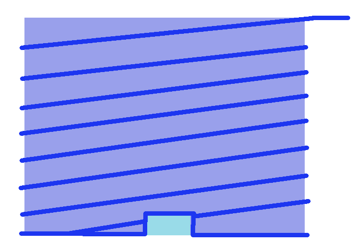
Currently no obvious info is given about Tabs when inspecting the Toolpath of the operation:

Nice to have this (or similar/better) way:

Summary:

  1. Manual Tab assignment for all Chains at once
  2. ‘Clear All Tabs’ button for Selected/all Chains
  3. More options for automatic Tabs (not in corner, just on straight, in pairs for different Chains, …)
  4. Remain the last used Chain coming back from ‘Edit Tabs’ (not necessary, if 1. is gonna made :wink: )
  5. Set Tabs along selected points
  6. Tabs also for ‘Contour Ramping’, …
  7. Treat checkbox ‘Apply Tabs’ in patterns view more save
  8. Show hint/symbol for Tabs together with Toolpath informations

Bye and thx, Harald

4 Likes

Hi Harald,

All sound like good options.

Another type of tab which I use occasionally for part off of thin wall parts are vertical tabs under the profile of the part to hold it until I can break the part off by hand. I have to create the geometry on the profile to get want I want and run a slitting saw on the profile with tabs drawn on it. It would nice to have something like the Tab page to machine the tabs as shown on the simulation below, without having to draw them. I guess they could be called vertical tabs.

Thanks
David.

Hi David,

good point. I just wonder, how much this strategy is used by others. But perhaps BobCAD introduce a new Mill 2 Axis Machine Strategy “Slitting Saw” that let us:

  • direct use a geometry (not having the need to create one from profile with offset or however you do that so far)
  • fetch a T-Cutter as slitting saw
    image
  • Configure “System compensation” left or right
  • Set the vertical tabs
  • Set Leads: where/how to get in and out

Wroom… the machine does the cut :slight_smile:

Bye, Harald

1 Like

Right, the easier you can make changes via the feature wizard would be optimum for workflow.

Hello All,
back again :wink: and now closer evaluate V35 or BC4RHV3 I try to step through the topics with all the requests/whishes to get myself an update.

So to this Tabs topic, no enhancement was done in V35/BC4RhV3. Also no comment is given from BC-Team.

Bye, Harald

Hi,
I just wonder, why there is no “Apply Tabs” in ‘Profile Rough’ opoeration when using ‘Contour Ramping’.
image

Any reasons, why?
Regards, Harald

Hello Harold,

Hmm Ramp with Tabs. Not sure the application here because normally you are ramping at the desired ramp angle of a tool (Direct Z only plunge is normally quite hard on tooling). If you add a tab (Without a ramp angle) then you would then create direct plunge moves, and in wood you may be able to get away with this, but for metal you will end up with a fairly prominent witness mark along the flank of the tool I would think. This is why normally when cutting with a ramp profile and the part needs retained then users utilize an “Onion Skin” method where you leave a very thin layer around the bottom perimeter of the part. Simply don’t cut the part all the way through. I know when I am machining in aluminum or titanium and I need to separate out a part I leave .003-.005 inches of material at the bottom…then simply peel the part out when done. My most used method is to not cut all the way through, then bolt the part down from an interior feature, and then come back in with my finish pass that I run all the way through the part and separate it while doing the last finishing pass.

I suppose you could use a ramp angle on the tab and make it match the ramp angle you are using on the cut… This is the only time I know of that this has ever been requested.

I have created a simple graphic of using a ramp cutting method while having a tab with vertical leads…to me this motion would not be desirable when cutting parts. Maybe I am wrong…

Question to all users then is: How many people would utilize a path like shown in this image?

Front view of part (part is purple, tab is blue, toolpath is dark blue)

Hello Alex,
the best way to mill (deep) slots is using ramp operation, as with each passage the tool is smooth on its way. Just plunging gets almost hard to the tool and it isn’t that much faster as ramping.

Yeah, sometime your approach is doing well. But a lot of times it isn’t that necessary to have smooth surface or it becomes more important to fix parts instead of being thrown away.

And your considered witness mark is also the case if just using the plunge method. So let the user decide, what kind of method and Tab will be used. Currently, for ramping with Tabs I have to create to operations. The first with ramping and ‘Bottom Allowance’ up to the height of the ramp. (or some remaining the depth cut height). The second with plunge, where it is then possible to use Tabs.

As for your image: yes, the toolpath should just follow the contour on ramping. It should work regardless if Tabs are done with 90° angle (like you drawed) or other ones as pictured below
image

Regards, Harald

1 Like

Hello Harold,

I will pass this over to the Dev team.

Thanks

Alex

1 Like

Hello Alex,
:slight_smile:
one more thought to ‘Depth of Cut’: can you also suggest, that there will be the possibility to define individual step sizes. Example:
8 steps, each defined with step size
image

Regards, Harald

1 Like

Hello Harold,

I will make sure that gets a feature request as well as long as it’s not already in there :wink:

Alex