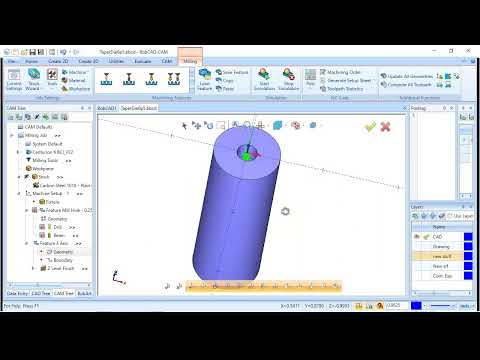
I selected a surface inside a bore for a 3D Z-finish operation - to contour part of the bore. The generated tool path is on the wrong side of the surface. How can I get the tool path to be generated inside the bore rather than inside the body of the part?
I would suggest selecting the whole model and then using a boundary (top of edge of this bore) so it knows about the whole model and where to go!
Thanks for the suggestion, I will give it a try.
I could not find a way to get the desired results by selecting the solid, and trying various boundaries.
The hole has a taper from 0.266" to 0.257" and I have an 0.250" bull nose end mill (0.045" radius). I get a little tool path in the hole, but it doesn’t go in very deep. I’ve looked for some sort of tolerance or clearance setting that may be holding things up, but can’t find anything that helps.
I just tried changing the tool to 3/16" with a 0.030" radius and the tool path goes deeper, but not quite there. A friend ran this on Surfcam using the 0.250" tool, and it worked just fine. So, anyone know what I’m missing to get it to work here?
Tried changing between “tool tip” and “tool center” - the tool path won’t go in deep enough to mill the feature with either setting.
Suggestions anyone?
Jason,
I sent the part file via email - in case you didn’t receive it, I will put it here also, if there is an option to do so.
I am using Version 32
TaperDie6p5.bbcd (333.5 KB)
I helped this user in another forum. Maybe this can give others a heads up here…
The tight space needs a tighter tolerance to be able to calc the toolpath… The video kindof walks through what he and I did in the other forum…
Added Note:
The Continuity thing at the end had nothing to do with the toolpath. That was just for a discussion I created with him. Added fun!
Anyway…
As a followup on this file, the best practice of selecting the entire solid body and using a boundary seems to produce erroneous toolpath “avoidance moves”. The solution was to select only the inner surface and utilize the "inside"option of the older zlevel finish feature and up the features tolerance to .0001
I went over it pretty good. Didn’t find any geometry errors.
He then wanted to address multiple G03 moves output for each z level move after the changes.
I pointed him to line 204 in his post to get his desired 1 G03 per z level move.
Had to drop this for a while, but took a look at it today.
Changing line 204 in the post doesn’t help any - just means that “G3” is printed on every line (telling the post G3 isn’t modal just means that it thinks G3 has to be printed every time). I haven’t analyzed the G code to see what the three G3 lines are really doing. But, this is a cylindrical hole, it should only take one G3 line to mill a circular path in a cylinder. It may be that the three lines are equivalent to a single line, but why break it into three lines?
As to my original problem, changing the tolerance to 0.0001 does fix it - I just have to manually adjust the z-depth because the software can’t seem to automatically mill the complete surface that I select.
Thanks for your help.
The line 204 suggestion was to change it to “YES”.
in my post it is set to no and when i posted your file i got 2 or 3 G03’s per Z move.
Changing it to YES, i reposted the file and got 1 G03 output for each Z move.
So if you aren’t getting that, then that can be pursued here. There are others that can help.
Gonna need to take a look at your machine file and post processor.
“”"“Bobcad can’t automatically toolpath my surface”""
Yeah, sometimes you have to tell it what you want… but again, the tool won’t plunge its tip PAST the end of a surface unless you manually tell it to. That is sortof by design. You almost NEVER want toolpath to go past a surface definition.

