A cnc machine is controlled by a computer that is connected to motors and motor drives that move the physical components of the machine. The positions these components are moved in are defined using the Cartesian Coordinate System. The machines physical axes typically align with the X, Y and Z axis of the Cartesian Coordinate System. This allows the machine to move either the tool or the workpiece into a position in 3 dimensional space.
The instructions that tell the cnc controller what and how to move are defined in a text file called an NC or Gcode program. The nc program will contain coordinates as to what, where and how the machine is to move so the desired part is created using the tool and the material mounted in the machine. This document covers how the machine locates where to cut.
When a CNC machine is powered up, they will commonly need to be sent to a home position. This is a position on the machine where each axis will move to so that it can establish a known location (zero) for all components.
For a common Vertical Machining Center (milling machine) this would have the machine move:
● Z Axis – Up to max limit (This is the spindle axis. It moves up and down on a VMC)
● Y Axis – Forward or back to max limit. Direction will be dependent on how the manufacturers setup the machine.
● X Axis – Left or right to max limit. Direction will be dependent on how the manufacturers setup the machine.
For the remainder of this document we will assume the machine will send the X and Y axes to the negative limit of the machines travel.
The following image illustrates the total travel envelope the machine is able to operate in, as viewed from the top, with the X & Y zero being set at the machines home position (Bottom Left Corner):
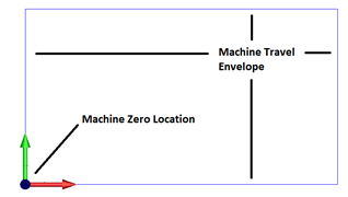
The RED arrow indicates the X axis positive direction (Left/Right with Right being a positive direction move), and the GREEN arrow indicates the Y axis positive direction (Forward and Back with a move going to the back as a positive move).
With the machine zero location established we can now begin to think about the coordinates inside the nc program. The coordinate locations that are contained in the nc program are also output in relation to a zero location that has been established in the CAM system for the part program. It is important to realize the coordinates from the NC program fit within the machines travel limits of the machine.
Let’s think through a simple example to illustrate this point. Below is a square part that measures 2 inches wide (X Axis) by 2 inches high (Y Axis). The zero of the coordinates for this part is directly in the center of the square (Shown by the intersection of the Red and Green arrows).
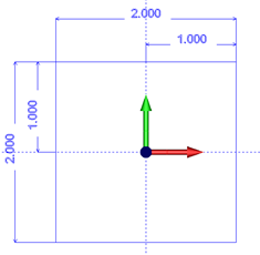
a list of the XY coordinates for each corner of this square starting from the 2 o’clock position and going counterclockwise:
X1.0 Y1.0
X-1.0 Y1.0
X-1.0 Y-1.0
X1.0 Y-1.0
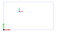
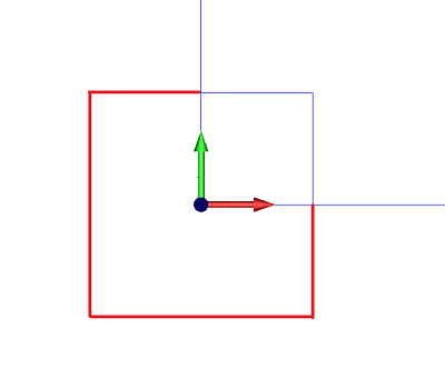
If we loaded an NC program onto the controller with the coordinates relative to the center of the part as shown, and we were running the machine where it’s zero location was set at a travel limit as previously described, the machine would not be able to cut the part as much of the part would be outside the travel limit of the machine as shown below.
This image shows the overall travel of the machine with the square oriented around the machine zero location.
This image shows a zoomed in portion where the parts of the square in RED are outside the travel of the machine.
What are Work Offsets
Work Offsets are commands that allow the user to define different locations on the machine to be used as a XYZ zero location. Most machines have multiple of these Work Offset locations.
Fanuc is a common manufacturer of CNC controller and their standard work offset options are:
● G54 ● G57
● G55 ● G58
● G56 ● G59
Each of these work offsets have a table of values the users can modify to shift the XYZ locations from the machine zero to where you would like in the machine travel.
Example:
G54 X:x.xxx Y:y.yyy Z:z.zzz
G55 X:x.xxx Y:y.yyy Z:z.zzz
G56 X:x.xxx Y:y.yyy Z:z.zzz
These work offset values are modified in the controller, though there are special commands on some controllers that allow you to modify the value for each work offsets value in the nc program itself. These values are usually adjusted from program to program based on the requirements of where the part needs to be located inside the machines travel.
Using the Work Offsets to Define New Program Zero Locations
In this section we will use the Work Offsets (G54-G55) to define two new program zero location inside the machines travel envelope.
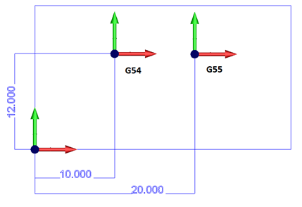
In the image above we see the two desired work offset locations (G54, G55) and the corresponding dimensions of these locations in relation to the machine zero location. By entering these dimensions into the machine controller Work Offset tables we can define these new zero location on the machine and then use these zero locations by calling up the desired Work Offset in the NC program.
Work Offset Table Values (In the CNC machine controller)
G54 X10.000 Y12.000
G55 X20.000 Y12.000
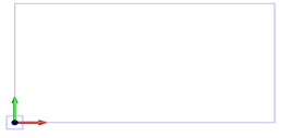
Now let’s go back to our example rectangle we were looking at before. Below are two images showing the orientation of this rectangle. The left is where the program is located if run from the Machine Zero location and the right image is if the G54 work offset is setup and applied in the nc program.
Machine Zero
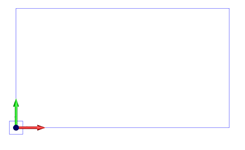
G54 Work Offset Applied