V35 lathe finish not following geometry

Hey all, new to BobCad
I use the same geometry for roughing/finishing, roughing gives me a good toolpath but finishing does not recognize the geometry, instead of rapid to the same start it drops down and wipes out all the features.

I get a lot of weird random geometry that it tags on to the start and or finish of my chain, I check for hairs etc but I can’t shake it.

Hello,

Sorry for the delayed response! Without seeing the actual .bbcd file, it is hard to know for sure what your issue is.

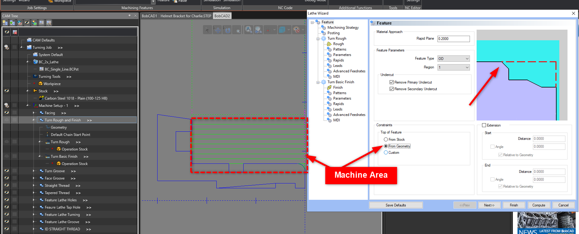
It sounds like you may want to review the “Rapids” and “Leads” page in the feature wizard for both Operations to ensure they are set up as intended. These pages control how the toolpath Enters and Exits the part.

I also wanted to point you to a couple of great resources for getting started in the software.

We have a new Online Learning Center called LaunchPad: https://launchpad.bobcad.com/

We have designed Launchpad by: BobCAD-CAM specifically to help users who are in a fast-paced manufacturing environment to empower them to learn on the go. Launchpad is our new learning platform that provides more segmented, digestible content with interactive features. You can take multiple courses and test your skills and knowledge with digital part file downloads, course PDFs and quizzes after each section to test your knowledge. This allows you to learn at your pace while applying your skills and knowledge right away.

Free Courses: Courses Page
Subscription Bundles: Courses Page

You can start with the V35 Getting Started Course for free here: V35 Getting Started Videos

This course has a Lathe Tutorial video along with other also videos to get you started.

Besides LaunchPad, we also have a Support Site: https://bobcadsupport.com/ along with other great resources that you can find in the PDF download link below:

BobCAD-CAM Online Resources 2023.pdf (208.5 KB)

Welcome to BobCAD! I hope these resources prove useful in your learning process!

Don’t forget to contact our support team as well if you ever need any further assistance with the software!
Phone Number: (727) 489 – 0003
Email: support@bobcad.com

Thanks for the reply.
The parts is long since out the door and I forget everything what we did to correct it.
I remember part of it was the stock was smaller than the part (because it was hex stock) and the tool wanted to follow the stock instead of the wireframe.
The problem was with the geometry, not the toolpath.
If I run into it again I will post a file.
Thank you
Ross

1 Like

I have been using mill a long time now and recently doing more lathe parts. It seems it is trying to clear the part. The way I have gotten around this is by setting the rapid plane to zero, then manipulating the rapids and leads to avoid the rapid that seems impossible to get rid of. I’m not sure how it works in the background so i don’t know what it would take to fix, but seems like there should be a better way. As of now this is how I get around it. For the rapids I use defined point in Z-X or X-Z depending on the feature and use the backplot to get the numbers for that to avoid any excess moves.

Okay, thanks for the reply back. Next time, if you are able, attaching the file would be beneficial.

When you say, “trying to clear the stock”, do you mean that the toolpath is trying to machine the whole part rather than just a section of the part?

If so, on the initial “Feature” page of the Feature Wizard, you can set Constraints. If you are just trying to get a specific area of the part, use “From Geometry” or “Custom”. This will make a bounding box around just the selected geometry instead of the stock. Notice the Dotted Lines in the example pictures of the Feature Wizard.

It is hard to know for sure what you are asking about though.