Mill 2 Axis Profile Corner Type Issue

Hello All,

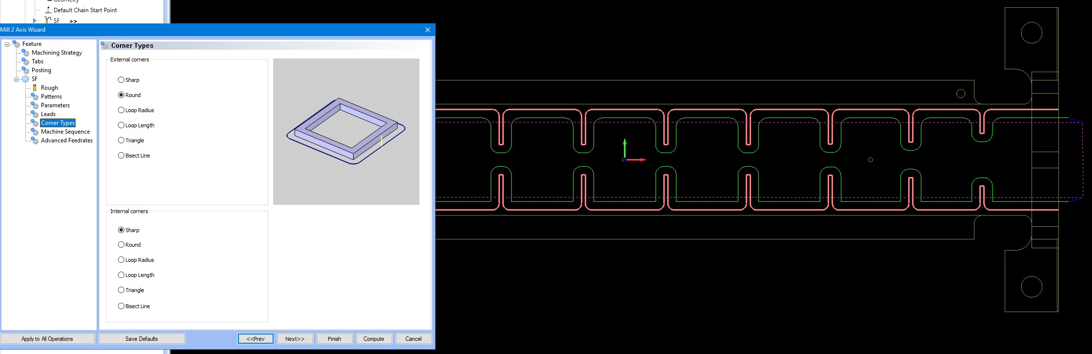
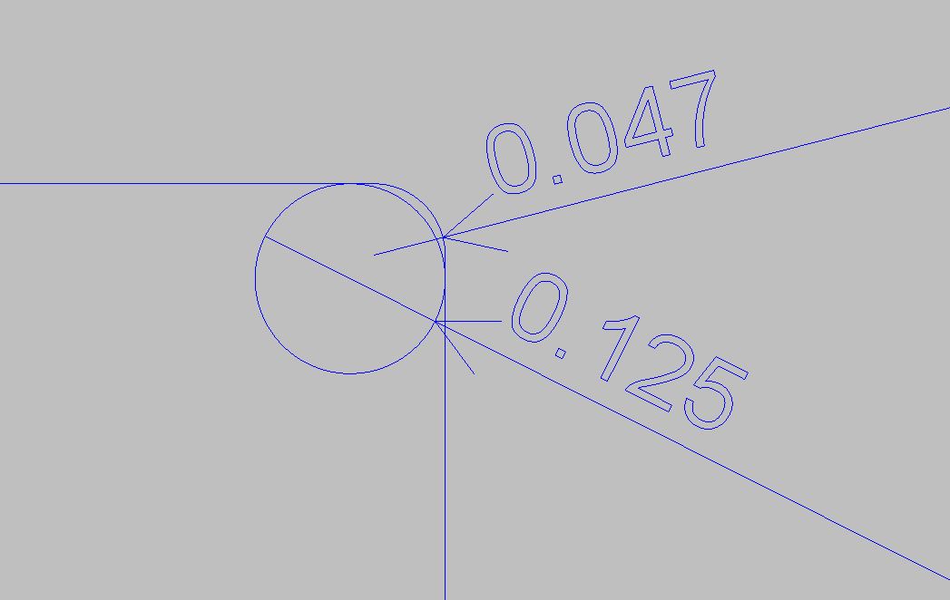
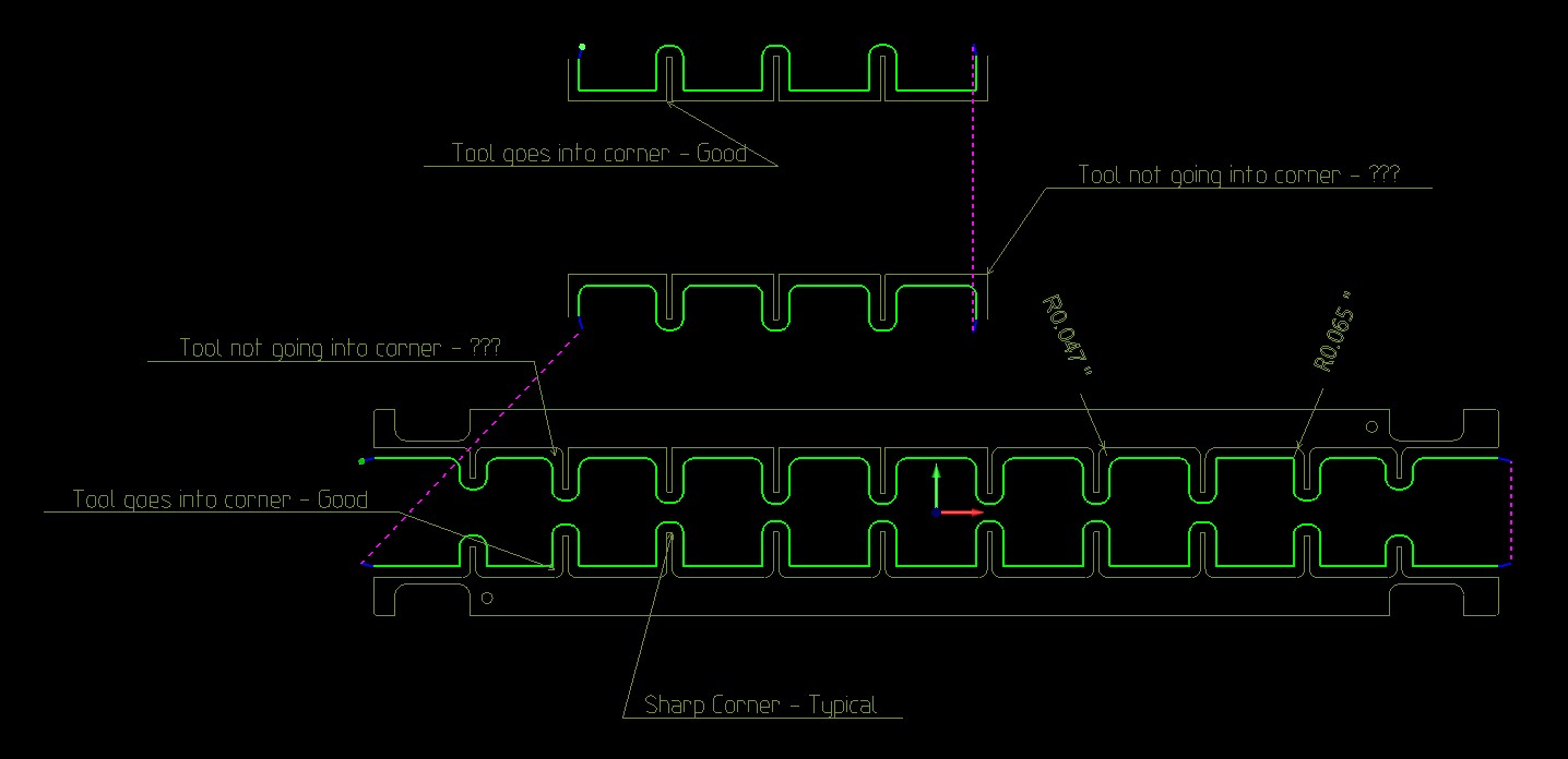
I often run into an issue with the “Corner Type” when using Mill 2 Axis Profile. Some internal corners will be rounded, leaving extra material. Per the screen shot below, the internal corners are sharp and external corners are round. The cutter is a 1/8" Endmill and the internal radii are .047". Stock on wall is 0. I tried using different geometry, solid edge and wireframe, the result is the same.

Does this happen with anybody else. What is causing this ? The only way around this is to create radii at .065" (or slightly larger then the tool radius) for those internal corners.

@TheWeave, @nbischof, @Alex_Cole

I think I am understanding the issue, but correct me if I am wrong.

With an .125 tool, the smallest Radius that tool can leave would be .0625. So if those internal Corners are .047 Radius, you would have to pick a tool with a diameter of .094 to leave that sized Radius. Or you would use a smaller tool, like a .0625 and that would be able to fit into those corners. See the attached image as a visual of what is happening.

The Corner types aren’t really doing anything for you here and when I train people I tell them to normally just leave it set to Sharp on both Internal and External. The system will put the tool as far as it can possibly go into the corner.

Hi Mike,

Thank you for your response.

There is something not right about this. The lower profile is different from the upper profile. Should be the same, since the geometry is.
I think the system should output a sharp corner when set to do so, unless there is a good reason prohibiting it.

Usually External Corners are set to Round to eliminate burrs on outside corners that are sharp.

David.

I think what he is saying is that he is getting two different results with one setting on the internal corners.

1 Like

Corner types are only applied to two lines that intersect, and not when the geometry has a radius in the corner. Your geometry shows that you only have 1 “Corner” and those are on the bottom profile, and they are external corners. In your picture it shows you have External corners set to Round…and that is exactly what the system is doing.

Now for the internal corners: As Mike said, your tool is larger than the radius in the corner, and since the geometry has a radius the corner types option is not applied. This is why you are getting a 'Sharp" corner, because the system is putting the tool as close as it can until it hits the tangency of the two lines on either side of your radius.

So you can see the system is applying the logic as designed. I know the developers have been working on corner detection because they just implemented new logic for the “Corner Slowdown” option however that is not applied to the “Corner Types” function at this time as far as I know.

I hope this helps.

Hi Chris,

That is what I am pointing out. Thank you.

For the screen shot below

“Corner Types” - “External Corners - Round” - which are all good, exactly what I am expecting. The geometry for the external corners are sharp corners.

“Corner Types” - “Internal Corners - Sharp” - different results, whether the geometry has a radius on the internal corner or if it is sharp. Note, to get the internal corners to be sharp, I need to set, “External Corners - Sharp” :thinking:

@Alex_Cole, @MikeD

Part File
APM Corner Round Topic.bbcd (371.7 KB)

1 Like

@Alex_Cole
about your info: such and several other is missing in the online documentation.

image
image

Basically, it can only be a matter of different methods of processing a corner. The result should always be roughly the same: namely, as drawn and after the best possible utilization of the cutter geometry. But exactly there (and in several other places) the documentation is unfortunately silent.

Haven’t had time to look into the different options in more detail yet :frowning:

That seems to be a bug, isn’t it?

1 Like

I think this is a bug.

A 2D contour is elementary for cam systems and shouldn’t have to deal with issues like this. Reduces confidence and you always have to double check your toolpath.

Hopefully BC will take a look at this.

David.

1 Like

in the instance that you are showing…sharp vs. round…i think the problem you are having is your thinking geometry…sharp or round in this instance refers to the tool path alone…where it either makes a 90 degree in said corner or a sweeping path around corners…on external corners for example i’ve found that using a round corner even tho my geometry is square will result in less to no burrs being generated on my corner because even tho it’s a square corner the tool path swept around that corner and took the burr off

@Bigman
yes, it can be assumed that the different methods make different toolpaths. However, with respect to the drawn geometry, neither one nor the other may give a fundamentally different result. Except it is pointed out that various parameters make a contour deviation, because with it e.g. the machine movement is more fluid.
If such things are not explained in the documentation, you have to guess and try. Both are not very pleasant and partly also insufficient. This is what I tried to point out three posts above.

Hello,

It looks like this might be a bug with the “Round” corners.

I am not sure how exactly they decided to specifically define an external or internal corner.

I will get more clarification on this with our dev team and will submit this to them to take a look at.

Thank you for this example! It shows the issue clearly.

Thanks everyone for all the feedback on this! It is greatly appreciated!

2 Likes

Hello @TheWeave,

Any report on this issue. Was this fixed in V34 ? Or has there been improvements ?

I am still using V33 and just recently I got reminded of this issue, as explained above in my posts. Drawing 30 radii in geometry that at times is not tangential in BC is not pleasant, you got to get creative and do extra time consuming steps.

Thank you,
David.

Hello,

I have reviewed the report that was submitted. The status on the report says “Work In Progress”. This means that they have reviewed the report and are working on fixing the issue.

I will put another note in the report saying that you were wondering if this was fixed in the newer version of the software.

Let me know if you had any further questions on this!

1 Like

Hi Paul,

Sounds good, look forward to this being solved.

I do have a separate feature request related to corner machining for profiling that I will put together later and post.

Thank you.

Hi TheWeave,

I upgraded from V33 to V36 and I just noticed that this issue has not yet been solved. It has been a good while and one would think it should be easy to solve. Please let us know of any BobCad-CAM progress on this.

Thank you,
David.