
I have been running Mach3 OEM as my machine for previous 3-axis work. I just have a inexpensive China Zone 6040Z 4-Axis machine that up to know I have just been doing 3-Axis work. This is a hobby for me. An expensive one! Just upgraded to 4-Axis Pro and going through the training videos. I understand that I need to select a machine with 4-axis capability. I do not see a 4-axis MACH3 option. Any idea what I should use?
Hi MS, that sounds like an interesting challenge. I just did similar with an anilam control. since you just bought 4pro, they owe you a post processor. find your 4th axis commands, learn how to program four axis moves in the gcode that mach understands, then you can tell the BC postprocessor team how a rewritten mach OS needs to behave. I dont know what mach can do, but the BC postprocessor team is really good at making their postprocessor create whatever gcode you need, even if your control wants conversational psuedo-gcode. good luck
1 Like
Mach3 and Mach4 both happily accept ISO G code, eg, Fanuc.
Mach3 and Mach4 are both 6 Axis Simultaenous capable so IMHO you should either just go with the Mach3 PP that you are currentlt using or you can try the BC_4x_Mill Post Processor, it is already setup up for 4th axis use with the A axis rotating around your CNC Machine X axis.
2 Likes
The Mach3 post that installs with the software is already setup for 4 axis output, you just need to select a 4 axis machine in the software.
So if your machine is a 4 axis rotary, with the 4th axis being on the table along X you can use the BC_4x_Mill machine and select the Mach3 post processor.
If your machine is a rotary along Y instead of X you can select the Haas_4x_Mill_B that comes installed with V34 and select the Mach 3 post.
If the 4th axis is in the head then you would need to have a custom machine built for this configuration that can compensate for the pivot length of the head.
BOBCAD’s support team gave me the same direction. I just tried my first 4-Axis project and it would not let me select “TURN” or “MILL-TURN”. Only Mill which I believe will not do 4-Axis. Any ideas?
FYI, I am using a in-expensive China Zone 6040Z table-top miller. Which, for what I do I am pretty happy with. It is a normal 3 Axis with a rotary accessory that mounts on the table to provide the 4th axis. I believe BC_4x_Mill and the Mach3 OEM is the correct choice for me.
So, I just selected “Mill” in the Job creation and discovered that later in setting up th mill process I could select 4-Axis milling. So, I guess I am OK. Took the first job through simulation. Thanks for your help!
1 Like
Hi Alex! I am getting closer. But still not able to get a simple program to work. See attached files. I appreciate any guidance you can give me.
Simple-4-axis-file-not-working.pdf (343.2 KB)
4-Axis-Try.bbcd (3.3 MB)
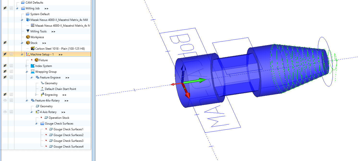
There are a few things to consider when creating the CAM tree and defining features for a Y axis rotary.
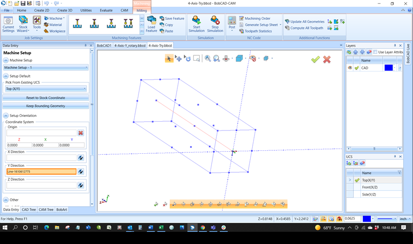
- First you want to make sure that the Y axis of the Machine setup is along the rotary axis of the part, as shown below:
To do this Right click on Machine setup in your CAM tree and select Edit
Then click in the box next to the Y axis and select a line that you want to be parallel to your rotary Axis.
Also note that if the Machine setup is not placed on center line, ie. on the diameter, you would need to apply that shift in the work offset section, so that the model is shifted to the center line for simulation and toolpath calculation.
- The next thing to consider is in the rotary axis feature itself. Make sure that the Y axis is selected for the rotation axis as shown in the image below:
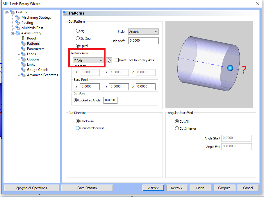
The same rule applies for the case of having the machine setup not along the center line, the shift must be applied to the Base Point defined on this same page shown above.
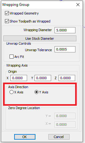
- The third thing to consider is in regards to wrapping groups. When Adding the Wrapping group, you again have to make sure that the rotary Axis is set to the Y axis.
Here is your sample part with these corrections made:
4-Axis-Do.bbcd (3.2 MB)
Alex, Thank you for responding so quickly. Would love to look at the file you sent but I could not use it. I am running V33, You must be on V34. Can you convert this to V33?
So, I tried your suggested changes and I must be missing something. Here is the toolpath which is not correct.
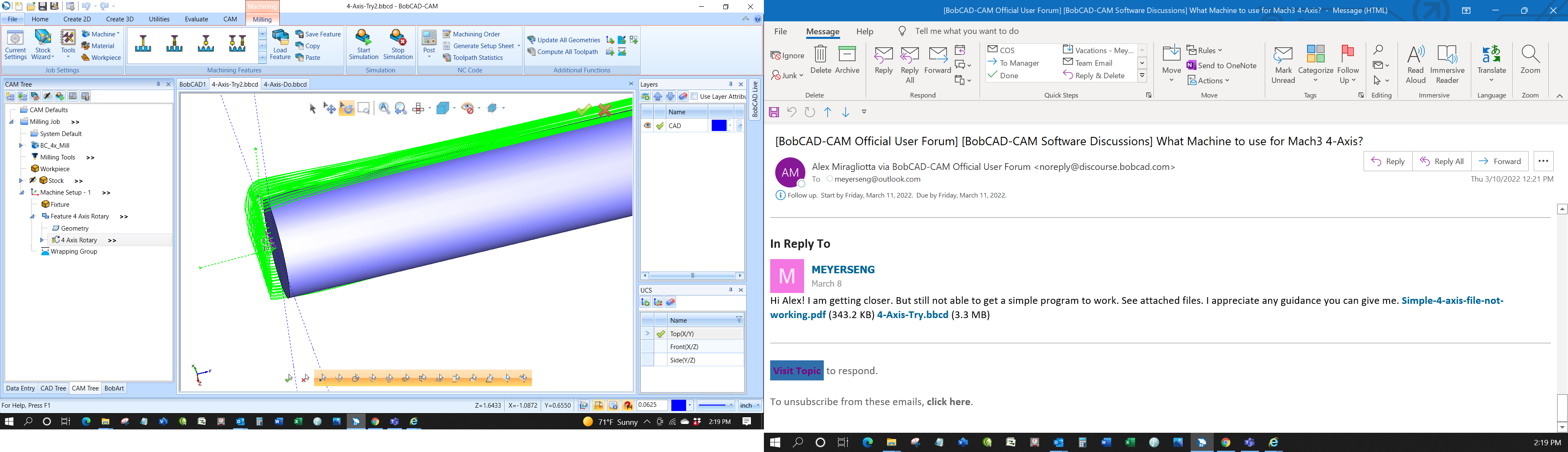
Here is the file with your changes.
4-Axis-Try2.bbcd (1.3 MB)
Appreciate your help in figuring out what I am doing wrong.
Best Regards,
Tom Meyers
You may find this helpful - workpiece orientation corrected …
If you need more information, do not hesitate to ask me
4-Axis-Try2_Y_axis_V33.bbcd (3.6 MB)
Luděk
1 Like
You’re welcome Tom,
Here is the file for V33:
The BC_4x_Mill machine is set up for A axis rotary around the X axis so this file is set up for X rotary:
4-Axis-X_rotary.bbcd (3.4 MB)
This file is set up for B axis rotary around the Y axis:
4-Axis-Y_rotary.bbcd (3.4 MB)
Alex, Those work, Thank You! One more question, when I set my zero reference do I set the Z point equal to the point of the center of the rotation? Or should I change the reference point to start it at the outside of the stock?
Svoboda, Thank you! But, that file would not simulate or post process. Appreciate you attempting to help!
That is up to you, either method will work, however it must match how you plan on defining it at the machine.
Defining it along centerline makes it very easy to program in bobcad because you don’t need to think about applying any of the offsets I mentioned in my previous tips.
Alex, So I finally finished my taxes and got back on this project. Your files work great. So I decided to compare your and mine to see what I was doing wrong. The CAM setups appear to be identical. Your instruction below was one of my issues.
- First you want to make sure that the Y axis of the Machine setup is along the rotary axis of the part, as shown below:
To do this Right click on Machine setup in your CAM tree and select Edit
Then click in the box next to the Y axis and select a line that you want to be parallel to your rotary Axis.
I realize now that when you do this properly, you see the following.
Once I did this the toolpath worked properly.
When you go back into this setup, the line reference is gone. See figure below. I believe BOBCAD should fix this.
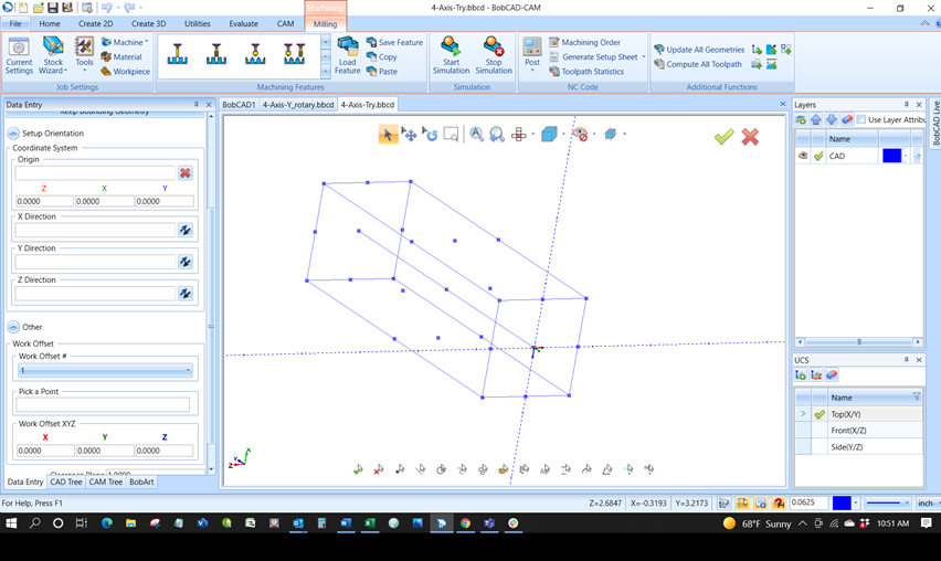
However, My project will still not simulate. See Figure below.
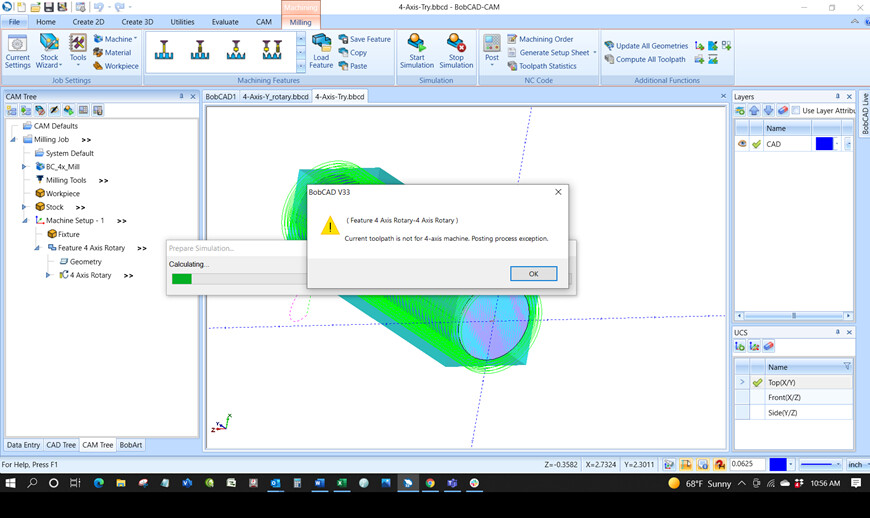
What else did you change???
After you change your machine setup so that the rotary is along Y you need to also update the feature to use Y as the rotary axis and recompute your toolpath:
Alex, Yes, that is and was in the correct position. What else did you change?
That is all you need to define for Y axis rotary,
Setup with rotary around Y
Define rotary feature around Y
update and recompute toolpath
There is no other setting to change.
Here is the part again:
B axis rotary around the Y axis:
4-Axis-Y_rotary.bbcd (3.4 MB)
Can you send me the part where your at so that I can see what is missing?
Your image shows that you have an X axis rotary machine selected.
In that case you would Setup with rotary around X
Define rotary feature around X
update and recompute toolpath